The Barncat Battery- No weld/no solder

file.php

Loose friction fit of the inside Cu Rivet against the inside wall of the larger threaded Cu Bolt is just asking for weaker/inconsisent contact ... NOT good. That SS Coil Spring is not a good conductor. What am i missing ??
SafeDiscDancing said:
Well, I guess I'm your biggest fan. (referring to Barncat)
Ditto that for me 2nd in line!

He's still in the beginning prototype development stage ... so far it looks to have potential as another pack fabrication option for certain applications. Do naysayers feel threatened that spot-welding may go out of favor because of KIS that is less labor intensive, requiring less equipment, less materials, less skill, but functionally just as valid for its application.

Barncat has never implied nor has anyone else that his concept will replace the need for spot-welding pack fabrication. IF his Calling Card were CoolCat instead of Barncat then maybe, just maybe, Chalo and Hillhater would be a little more receptive/positive in seeing its potential ... as is spinningmagnets previous more positive post :thumb:
 
Re fit ... you are right, “loose” would not be good. Really, need a clean sliding fit ... picture a 1/8 inch hole and 1/8 inch shaft ... so there would be good contact, but allowing movement.
 
footloose said:
Re fit ... you are right, “loose” would not be good. Really, need a clean sliding fit ... picture a 1/8 inch hole and 1/8 inch shaft ... so there would be good contact, but allowing movement.
Seriously ?! ..sliding fit ..and good contact....do not match up to a reliable result.
This type of “pressure pin” has been discussed before. It needs a positive , flexible, (braid type) connection between the bolt and the pin inside the spring.
Then it is all getting very complex compared to a simple welded pack.
 
Hey guys- I'm finding the debate quite entertaining. I'm going to digest the input and formulate a sort of global response... but keep it coming.

Let us not, however, lose sight of the fact that:
MY BATTERY PACKS ALREADY WORK!!! These are prototypes only in the sense that they don't look factory made.

The naysayers: "but it won't work tomorrow". Clearly a valid concern that i share. But I've already had a lot of "tomorrows". Shall we not bear in mind that even the industry made stuff has a finite life? And you can't take that apart for repairs.

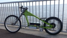
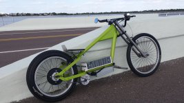
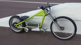
Another 25 miles on the Stingray this afternoon...
 

Attachments

  • 20220216_155648.jpg
    20220216_155648.jpg
    3.6 MB · Views: 599
  • 20220216_155807.jpg
    20220216_155807.jpg
    3.2 MB · Views: 599
  • 20220216_155823.jpg
    20220216_155823.jpg
    4.1 MB · Views: 599
spinningmagnets said:
Many small devices run off of 1.5V to 4.1V, so intermittent lack of contact can occasionally be an issue.

A pack that uses 48V or more would be unlikely to suffer these types of problems, as higher voltages can flow through "less than perfect" contacts.
Hmm ?.. 48v ?..true for “full pack” connections...but no individual cell contact sees more than 4.1v across it . :wink:
 
Hillhater said:
Then it is all getting very complex compared to a simple welded pack.
... :mrgreen: :mrgreen: :mrgreen:

There is no such critter as a simple welded pack in comparison to other non-welded options such as NESE and Bc's prototype with explicit potential for certain applications ... i.e. 10S.

No one has ever suggested it's a viable option for a 20S end-to-end cell application or even a 12S 18650 battery pack ...

file.php


VERY COOL, KUDOS, THUMBS UP ... very much like the clean low lines ... it's beaut-e-full
(maybe a rear fender, but that would detract from a "less is more" minimalist design style)
Instead KIS minimalist trailing flap behind seat ... gives new insight into lifestyle of Barncat.

Must be some Swedish KIS ancestral spirit in your 'frame' of mind) :)
(also KIS B&W background line staging for your impressive digi-image)
 
The biggest "Fear Porn" we seem to hear as it relates to pressure contact battery setups is the worry about "dimpled cells".

Welding to a cell means you are up front potentially damaging a cell.

Pressure contact cells have no up front dangers, but the "Fear Porn" is that a big bump with be so intense to actually "dimple" a cell.

Seems to me there should be some data "somewhere" that lists the maximum pressure a cell can endure before getting a "dimple".

My "guess" is that only a few pounds of pressure is needed for successful functioning of a pressure contact battery.

You do not need the cells forced together with extreme force which might induce a "dimple".

And this is where a very precisely accurate spring pressure could exclude the worry about over tightening.

The other option is wisdom... just don't be foolish and over tighten the cells.

But that assumes people have good sense which in our world is no longer a base assumption.

file.php


If you look closely here the parallel connector is a mat cloth metal and it would be my "guess" that it would provide a spongy interface that should soften any vibration and spread out the loads.

So that is another feature here of benefit to maintaining a constant contact pressure.
 
SafeDiscDancing said:
The biggest "Fear Porn" we seem to hear as it relates to pressure contact battery setups is the worry about "dimpled cells".

Welding to a cell means you are up front potentially damaging a cell.

Pressure contact cells have no up front dangers, but the "Fear Porn" is that a big bump with be so intense to actually "dimple" a cell.

The other option is wisdom... just don't be foolish and over tighten the cells.

But that assumes people have good sense which in our world is no longer a base assumption.
SafeDiscDancing said:
file.php


If you look closely here the parallel connector is a mat cloth metal and it would be my "guess" that it would provide a spongy interface that should soften any vibration and spread out the loads.

So that is another feature here of benefit to maintaining a constant contact pressure.
me thinks a few naysayers are making a mountain out of a few pocket gopher mounds :wink: ...

GopherField2.jpg

Does Hillhater now require Barncat to do some 'field' tests over pocket gopher mounds :wink: ... or maybe a bumpy mountain bike hill-hater trail ??

Some are going out of the 'way' to dissuade what has definite application. Barncat has already proven it's success with road tests, but now must do some bumpy field tests and still may not satisfy Hillhater propensity for spot-welding.
 
Hillhater- your inference here is that DIY lithium ion packs with literally hundreds of spot welds and dozens of tiny soldered wires connecting fragile circuit boards all contained in dubious insulation and questionable enclosures is 100% infallible.

To put it charitably- that's not true.
 
I'm starting this post at 12:18, in the event others post in the interim...

To recap- I'm not here to make converts. If you like what I've been up to- cool! If you don't- no problem.

This has thus far been valuable as sort of market research. I'm not selling anything directly. I have no current plans to buy and learn to program a large 3D printer. There has to be a niche market for this, but there are liability concerns as with any product and the profit margins are unknown.

I defy anyone to create a simpler more user friendly DIY design however. Low tech is not always bad. And it would look totally pro with a few more tricks I have up my sleeve. If some entity wants to run with this all I ask is that you do the honorable thing and cut me in.

NO PRODUCTS ARE 100% SAFE. You can choke to death on a hotdog or trip over a shoelace going down the stairs.

For the armchair quarterbacks: in eight months of work I've gone from zero to building 3 successful performance ebikes, all of which are pictured in this thread and one of which has probably near the best power to weight specs out there, I've devised an improved freewheel with sprocket, and built and tested these two batteries. Do I wish I had two more years of testing on those? Yes, but my time machine has not been perfected yet 8)
 
Just a fact bak 18650 25a cells are a bit wider then most as I got the N.E.S.E. 14s 8p and they wouldn't fit till I took the wrapper off. Augst said if he know he could have made them a percentage bigger.

Hey barncat I call photo shop. I need to get a test ride to make me a believer .
 
eMark said:
Hillhater said:
Then it is all getting very complex compared to a simple welded pack.
... :mrgreen: :mrgreen: :mrgreen:

There is no such critter as a simple welded pack in comparison to other non-welded options such as NESE and Bc's prototype with explicit potential for certain applications ... i.e. 10S.

No one has ever suggested it's a viable option for a 20S end-to-end cell application or even a 12S 18650 battery pack ...
? .. are you suggesting that a welded pack is no simpler than these “loose cell” packs ?
If so , just do s quick component count,..and consider that each separate component is a potential failure point... then do a size and weight comparison .
??...And incase you had not noticed , Bc’s packs ARE 20s and 15 s ! :roll:
 
Barncat said:
Hillhater- your inference here is that DIY lithium ion packs with literally hundreds of spot welds and dozens of tiny soldered wires connecting fragile circuit boards all contained in dubious insulation and questionable enclosures is 100% infallible.

To put it charitably- that's not true.
Nothing is infallible, but yes, multiple spot welds ( per contact) are much more reliable that a dry pressure contact,..
...but incase you had not noticed , your 20s,5p pack has 200 “dry” connections !
..and all things being equal all packs will need similar balance wires and BMS boards...if that is your point.
Welded packs do not require the same rigid supporting enclosure... and are frequently assembled using simple cell holders..
( and cell bonding is also commercially proven !
 
spinningmagnets said:
I appreciate your work, and I'm glad you posted here.

I second that motion.

We love the innovative and the risk taker willing to take an idea and run with it.

But I think that experience teaches us that those who are bold and dream great things will always suffer the attacks of those who take comfort in conforming to group opinions.

Having a thick skin is necessary if you take risks.

Barncat needs to start laughing at his critics. :lol:
 
To get a little more contact pressure between the bolt and the sliding tip you could bevel the end that pushes on the spring a little so there will be some sideways force. Making the tip off center would also do that.
 
My biggest concern would be corrosion at the tips into the big, flat copper busbars (?) where the pegs are spring-loaded; I could see them corroding over time and lowering the flow. But I think that could easily be solved, by making it a small space with an airtight cover out of plexiglass, and tossing one of those silica gel moisture/air packs into it.
 
Hey Barncat! Thank you for sharing! I absolutely believe that a non-welded pack can be robust and provide life for as long as a welded pack. I built a 3D printed pack with nothing more than the same copper braid, some 3d printed plastic and screws to provide compression. It works great! Click this link to check out the design..

The pack I built used nothing but recycled batteries, and were painfully tested one by one (I won't do that again... I will run them and replace them if they suck). The best part is swapping out bad cells has been super, super easy. The worst part of the design linked above has been the mounting options. I have used all manner of straps and zip ties to keep the individual "packs" together and then using even more straps to mount the sucker to the bike. Luckily I have an industrial sewing machine and making 1" nylon braided straps is simple... but the whole thing is far from ideal. Your design solves several problems I have faced during my build.

I have a 3D printer, a CNC machine and I would like to make a pack with this method in the coming weeks. Right now I am working on a steer roping sled that my buddy uses to practice roping. He has been using a gas powered winch and would like to convert to electric motor/batteries to get more torque. I may use this design, but as you said... dimensions are critical.

Reasoning about your design pictures and what you have said still leaves me with some questions. You load from bottom up, I think... Do you compress after each layer build or wait to compress until the end?

When do you attach the bus bars at the top during construction, before the cells have been loaded?

Where should I start in your opinion when drawing this up in CAD. Ie. What dimensions are absolutely critical to nail? My gut thinking based off the little I know says the width is more important than the length as you have some adjustability from the top with the screws... I also believe in shims and side to side movement could be eliminated with foam or plastic if needed. Awesome project, I am totally jazzed to try out another method!
 
Barncat said:
I've ridden the green pack hard the equivalent of Tampa to Santa Fe with zero issues and still good as new.

Barncat -- thanks for posting your design! Wonderful to see an innovative approach, achievable in a reasonable workshop, that works. Maybe most enjoyable -- it got my brain working, which is a rare enough event.

Like Fechter says, "One test is worth a thousand opinions." If you've done mileage equivalent to Tampa > Santa Fe, the design works. In fact, I'd bet a buck that you make it to the virtual Pacific without problem. And probably back home again.

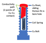
Although my spring-loaded-copper-rivet-in-bored-out-copper-bolt idea is Rube Goldberg overkill, I tweaked it based on Fechter's suggestion on how to ensure a good current flow path. Including it here just for reference. Current flows copper-to-copper; the spring is not relevant to the current path, it is only for compression.

Screen Shot 2022-02-18 at 9.51.11 AM.png
 
footloose said:
Although my spring-loaded-copper-rivet-in-bored-out-copper-bolt idea is Rube Goldberg overkill, I tweaked it based on Fechter's suggestion on how to ensure a good current flow path. Including it here just for reference. Current flows copper-to-copper; the spring is not relevant to the current path, it is only for compression.

Why even have a slip fit?

file.php


Separate spring from the connectivity path entirely.

This creates a direct contact with the cells and an unobstructed path for current.

Also, if over time you get corruption on the copper just give it a light sanding and you are good as new.

That's just a 10 AWG wire soldered to a copper disc.

Just flair the 10 AWG wire into a radiating star pattern and solder flush. Use a sander to smooth it out a little.

Then play around with different springs to find the perfect contact pressure.

Mounting it is as simple as "flat wall"... then "drill hole".... "insert wire with spring".... make final connections externally.
 
spinningmagnets- thank you for your diplomatic neutrality. You of course know a thing or two about battery building, and while I don't know the whole history of this website, your and others efforts to make it possible are greatly appreciated. This is a great way to document projects and passionately debate topics.

999zip999- I assume you're joking about photoshop :) . I may get some video clips posted soon.

Hillhater- yes, my approach is unorthodox, but I purposely withheld this reveal for a long time. Please reread my original post if you wish to understand my rationale.

And guys- I've reduced a rugged full sized battery box (for 18650 or 21700 cells) to what I believe is the simplest lowest part count possible. So far- I've not felt a need to try to use spring based contacts but by all means keep thinking it over...

Given that I've determined shoulder shorts not to be a problem, the whole crux of this concept is the +cathode, and whether it will deform either instantly and/or over time. It would be nice if manufacturers made that part with slightly heavier steel. And there is a very slight variation from brand to brand. 21700 cells are a bit beefier, and with the larger cell end surface area I hit on using the flat copper braid for contact conformity and one presumes vibration damping. I arrived at that independently, but I'm certainly not the first guy to arrange cells end to end.
 
Barncat said:
999zip999- I assume you're joking about photoshop :) . I may get some video clips posted soon.
As a former photo.graphie instructor (and graphic designer) you have a special visual intellect that carries over into your e-pack concept design.

Especially liked this digi-image with its interesting diagonal background lines and complimentary simplicity as evidence of your artistic "seeing eye" for visual composition ... carries over into the minimalist concept of your packs' concept validity as well as your Coolcat e-bike. One of my student assignments was to submit a photo having no distracting background with interesting diagonal lines. This one digi-image would have deserved an A+ and it tells me enuf about you to know You are Legit, AOK, and then some :thumb: :thumb: :thumb: ...

file.php

Barncat said:
Given that I've determined shoulder shorts not to be a problem, the whole crux of this concept is the +cathode, and whether it will deform either instantly and/or over time. It would be nice if manufacturers made that part with slightly heavier steel. And there is a very slight variation from brand to brand.
That protective cap over the cathode shouldn't be a concern for "dimpling". The contact area is across the entire cap (as with your concept) so "dimpling" isn't even possible ...
footloose said:

Do an experiment by keep increasing the pressure on the cathode protective cap an old cell you can afford to waste. Think you will find out it takes by far more pressure than is needed in order to deform/crush that protective vent cap over the cathode.
 
monkmartinez- very good. You've already done some work in this area. Did you arrive at using the braided copper strip on your own or by seeing it used elsewhere?

Yes, arguably the best feature of my design is the customizable single large case which accomplishes several things at once. That will eliminate the complexity of your multi-part prototypes as you've said. The case still must be securely attached to your bike or machine. It would be easy to zip tie it to a rear bike rack for example. For my builds I either welded or bolted sturdy brackets to the frames as pictured previously.

The side walls and end walls must be very stiff. The clear polycarbonate (Lexan) lid pegs the cool meter, and the see-thru cells are the first thing people notice when commenting about the bikes out on the street. Humorously, many people have asked "is that solar powered?"..........

Polycarbonate is a miracle material IMO. DO NOT, I repeat do not, use shatter prone acrylic instead for the lid- that stuff has no place in this application- and I never use it for anything. Poly is explosion and bulletproof in adequate thickness, is easily drilled, sawn and shaped. It's not very stiff however, hence the aluminum angle straps on the wider gray pack.

Reread my posts for construction and tolerance specs. Avoid shims. Absolute minimum clearances must be held- easy once you know your printer, which must be able to do at least 16" one way for 5s/layer.

Whole case is top loading with all internal and external buss plates in place and screws backed off. Be damn sure you design the internal plates (which are hand dimpled for contact) to be captured so they can't move and short your whole pack.

Lay in the bottom layer of cells and parallel strips, add the
.032" Lexan insulator sheet, reverse cell orientation and lay down second layer, etc.... when you're done the top layer of cells should be about .005" proud of the case sidewalls (which allows the whole stack to clamped down). Screw the lid on snug enough to keep all cells flat and such that they can still move longitudinally. Adjust the screws and lock nuts from the bottom row up, then screw lid down tight. This all takes skill and feel. And used cells must be burr free with old weld tabs carefully removed and make sure the + ends have no flaws in the overwrap insulation. I do not use additional fiber or plastic ring washers.

Also since you're printing- add projecting insulator fins between the external copper bus plates.

You have your work cut out for you. A lot of measuring to do!
 
eMark- thanks for the thumbs up on my aesthetics and other support. I always strive for performance AND appearance.

I did experiment on junk cells and deformed some end caps on cells with my first crude prototype, with the screw points used as the contact surface. That idea was quickly discarded for the reversed screw.

As of this writing, I can't think of a tweak that will 100% eliminate the potential for deformation. All good so far but the wheels are always spinning (pun intended).
 
Back
Top