e-beach
10 MW
lwik said:So I ordered 4 left handed throttles Friday. should be a couple weeks I would think till I get them. When they arrive I will open them up and see what Hall sensor they use and order a bunch of those. I ordered a slightly different one then the standard. While riding on my bike trip after 40 miles or so I thumb starts to hurt in the spot that I keep it held down. Hoping this new one word better.
Left handed? Why the change from the normal right handed?
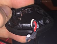
As for opening them all, just start with one and see what is in there. The chances are they all have the same Halls. Opening them all will only weaken the plastic nubs that keep them together.