torque arm picture thread

I'm posting here as a warning to anybody who might, like me, try out these torque arms from Amazon:
https://www.amazon.com/ColouredPeas-Bicycle-Accessories-Electric-Conversion/dp/B07XZ2JZ5R
31B4T7jZZ6L._AC_SY400_.jpg


I ordered two for a customer's project. They shipped fast, the price was right, and they looked a lot nicer than the photos. Crisp laser cuts and a nice black phosphate finish.

Unfortunately, they are 10.7mm across flats, making them approximately useless for a 10mm flatted axle. Don't try them yourself, please.
 
In order to save a few bucks i've ordered about 5 different brands of torque arms over the years and had the same result. No more..

Apparently cutting the correct diameter hole is impossible to do unless you are ebikes.ca, lol.
 
Laser cut from 304 stainless steel. My dropout has holes for a disc brake caliper and pannier, I used those to hold the torque arm. The torque arm is also extended backward to mount the pannier a bit further back because I carry a crate on top of it. A smaller piece of steel allows the weight of the rack to be pushed on top of the dropouts instead of just the screws.
IMG_20200317_115321.jpg
 

Attachments

  • IMG_20200317_115321[2].jpg
    IMG_20200317_115321[2].jpg
    2.3 MB · Views: 1,213
spinningmagnets said:
From DogDipstick

Thankyou for the credit. I did want to post here: For I did spend some time, on this aspect of my project, and am invested in my bike greatly. Looking at what others have done is very helpful. I also used some of the aspects of the "Eleek" ebike's swingarm mounts for a guide.

I do want to say: there is ALOT of cool stuff in this thread if you like making things with your hands. ...many have great, great designs.

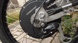
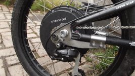
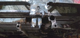
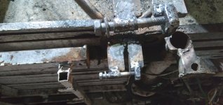
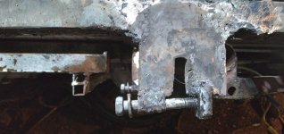
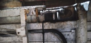
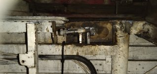
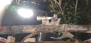
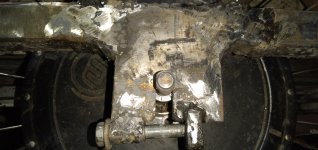
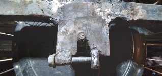
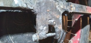
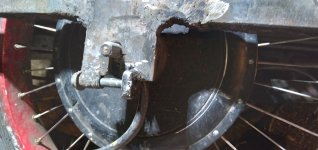
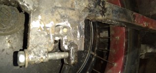
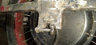
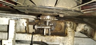
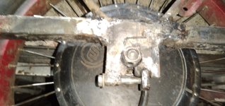
The req. were: I had a 135mm frame; I wanted to adapt a 150mm axle motor to: By extending slightly back, and down, with the stainless plates. Beginning with an open dropout 7005 aluminum frame ( Ironhorse Hollopoint)... I wanted a strong mooring with multiple points of contact that could take a load. I had run the 135mm axle motor for some time: and another Ebiker gave me those "U-Shaped" axle mounts, pieces cut by a laser.. I wanted to use them. I wanted pinch bolts, and to take up as much of the axle, outside of the motor, as I could.

Req:
-strong
-not to heavy ( Assy. is 3lbs total, 1/10 of the weight of the motor),
-act as a Tq. arm, on both sides, in the needs of handling power, while repositioning the bikes axle.
-not corrode, be easy to lift the motor in and out: be easily " bolt on construction", long lasting.
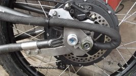
-shouldered bolts securely in the sockets milled to receive them,
-not be able to " Drop out" by any means ( 360* of metal around the axle)( pegs and weldments preventing that).. Fail safes.
-Easy to build, weld, and drill/thread/bolt with the simple hand tools I have.
DSCF4060.JPG

I certainly came first to study the designs others have put forth, here. I appreciate the history of others. Thanks for the reference. I can weld stainless easily at home, and do some rudimentary machining.

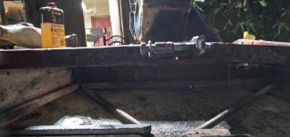
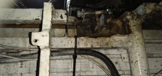
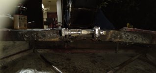
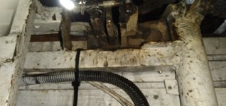
They ( the new axle mooring) have been tested, and seem to be working well. The 30 lb motor is almost twice the weight of the (bare) frame. I took a little adaptation for the chain to meet the freeweel correctly, and the 17T seems to have been a good choice for me. I still need to buy a good derailleur-mount tension-er, for I still have alot of suspension travel on the bike, and the front chainring is a three ring at the moment, pedals well. I might "form" another piece of custom stainless strapping for this purpose if I want to get rid of my derailleur placeholder, but because of the travel, and the assortment of rings, the bike has, I need the chain tension-er. .

Strictly a road traveling bike, now, given the constraints of the hub motors handling. I even have a little more room for a wider rear tire, now. Wheelbase has increased, 1" ( 25mm), fork angle has increased, 5*, ( from 19* to ~24*), trail is 3.65" (92mm). I will weld the pinch arm lever into place ( under the bobbins) once I have given the assembly a little more time to work itself into position. There are a couple of crucial plates welded on the back, inboard, that one cannot see, (a peg, and a triangle) to keep the motor from being able to move: They look great for a " bolt on" assy, and seem to be handling the load well.
 

Attachments

  • DSCF4076.JPG
    DSCF4076.JPG
    630.1 KB · Views: 1,206
  • DSCF4075.JPG
    DSCF4075.JPG
    616.1 KB · Views: 1,206
  • DSCF4074.JPG
    DSCF4074.JPG
    567.3 KB · Views: 1,204
Seriously nice work dog.

I keep wondering though, when will the motor companies change the axle design. The heinzman motors from 20 years ago had it right. This allowed regular 10mm round axles in the dropouts, but the torque arm had about 20 mm to grab on.
 
Here's a job I did for a customer that came out super tidy:

IMG_20220705_195912.jpg

I rotated the axle and double torque arms all the way forward, then centerpunched, drilled, and tapped M5 mounting holes.
 
Chalo mentioned Grin Technologies earlier. They make some quality torque arms for those that may be struggling with the machining side of things. I've used a few and also modified a couple for special use.

https://ebikes.ca/shop/electric-bicycle-parts/torque-arms.html
 
Just saw this for sell on eBay.
https://www.ebay.com/itm/325271242736?hash=item4bbbad47f0:g:9P4AAOSwj7Vexztz
Is one of our member selling these?
 

Attachments

  • Screenshot_2022-07-25-21-00-33-38_40deb401b9ffe8e1df2f1cc5ba480b12.jpg
    Screenshot_2022-07-25-21-00-33-38_40deb401b9ffe8e1df2f1cc5ba480b12.jpg
    714.1 KB · Views: 837
Here's an adaptation of a crappy, loose fitting torque arm used on a bike that can only transmit torque in one direction. I rotate the arm all the way forward before doing up the axle nut. I didn't feel like grinding the chrome off the fork tips to get rid of the lawyer lips, so I modified a flat washer to fill them in, and I use a couple of thin 6mm washers to fill the gap between the TA and the fender eyelet. I had to grind a relief in the TA to clear the bottom of the fork leg.

IMG_20220808_143412567_HDR~2.jpg

IMG_20220808_143543977_HDR~2.jpg

IMG_20220808_144239251~2.jpg

IMG_20220808_144225200_HDR~2.jpg
 
New Clamping / Pinching dropouts on SB Cruiser, partial crosspost to leave the info here for anyone needing a similar thing:
https://endless-sphere.com/forums/viewtopic.php?f=2&t=67833&p=1737527#p1737527

They're welded to the lower edge of the thick dropout plates, so they apply their force along the plates. My old inboard dropouts had the bolt thru an existing hole (because they were so hard my drillbits could not drill into them) on the "L" that presses along the entire length of the axle flats, but this did not apply the force evenly along the axle as it was to one side of it, and thus didn't fully clamp it flat on the faces of the dropouts. The outboard dropout never had a clamp, just depending on the several mm thickness of hard steel's tight fit against the axle flats, and the axle nut tightened against the dropout face.

Now the clamp is on both inbaord and outboard. The clamp is built with a steel tube that used to be the inner race of some small wheel bearings I saved out of damaged caster wheels, similar to these:
https://cdn3.volusion.com/nqeof.zmawn/v/vspfiles/photos/PB38-Q34-2.jpg?v-cache=1666181287

file.php


The bolt is also from the same caster wheel, so it fits the tube very closely, and is a typical steel marked 4.8 (Class 4.8 Metric Bolt). https://www.engineeringtoolbox.com/steel-bolts-metric-grades-d_1428.html


I would've used the nut, but they're very small and thin-sided, and the weld would probalby have penetrated into the threads. But I had some square plates about 1" x 1" x 1/4" that had a hole in the center threaded just like these, so I used two of those stacked together for thickness (more thread engagement).

The dropout plate is notched on the leading part, for the doubled plates to fit tightly into (to be tapped in by hammer so I don't have to hold them for welding, then the bolt is threaded in with the tube on it, so the whole thing is held in place for welding by this).

The tube is placed so it's rear end edge is just beyond the rear edge of the dropout plate, so the bolt head and washer clear the plate easily for isntall/removal.

The dropout itself is a pretty close fit, but not tap-in-axle-tight, to make it easier to get the wheel in and out whenever it needs to be, since the clamp will do the tight-fit job instead. Save me a bit of work roadside in the event I have to do a tire repair.

Just unscrew the bolt and pull it back to clear the dropout and put in or take out the wheel / axle.
 

Attachments

  • 20221023_190110.jpg
    20221023_190110.jpg
    2 MB · Views: 352
  • 20221023_190123.jpg
    20221023_190123.jpg
    2 MB · Views: 351
  • 20221023_190127.jpg
    20221023_190127.jpg
    2 MB · Views: 351
  • 20221023_190135.jpg
    20221023_190135.jpg
    2 MB · Views: 351
  • 20221023_190140.jpg
    20221023_190140.jpg
    2 MB · Views: 351
  • 20221023_190149.jpg
    20221023_190149.jpg
    3.5 MB · Views: 351
  • 20221023_190155.jpg
    20221023_190155.jpg
    3.5 MB · Views: 351
  • 20221023_190201.jpg
    20221023_190201.jpg
    2.9 MB · Views: 350
  • 20221023_190205.jpg
    20221023_190205.jpg
    3.1 MB · Views: 350
  • 20221023_190213.jpg
    20221023_190213.jpg
    2.8 MB · Views: 350
  • 20221023_190944.jpg
    20221023_190944.jpg
    3.9 MB · Views: 350
  • 20221023_190952.jpg
    20221023_190952.jpg
    4 MB · Views: 350
  • 20221023_190956.jpg
    20221023_190956.jpg
    4 MB · Views: 351
  • 20221023_191000.jpg
    20221023_191000.jpg
    2 MB · Views: 350
  • 20221023_191007.jpg
    20221023_191007.jpg
    3.7 MB · Views: 351
  • 20221023_191010.jpg
    20221023_191010.jpg
    3.3 MB · Views: 352
  • 20221023_191021.jpg
    20221023_191021.jpg
    3.1 MB · Views: 352
  • 20221023_191057.jpg
    20221023_191057.jpg
    3.1 MB · Views: 352
Yeah, I don't really do "pretty" very well, but stuff usually works. :)

(I could probably do it really pretty but that takes a lot of time and energy better spent on the zillion other things I don't have time or energy for either).


I wish I'd had longer bolts I could trust, so I could've put the "nuts" fully at the other end of the dropout plates, because where they are they are just barely far enough from the actual dropout to clear the axle shoulder thickness, so I can't (easily) use washers and other hardware on the axle on the inside of either dropout. I'd have to shave one edge off enough to clear the nut and keep them oriented correctly while installing the wheel, which is very difficult. So I skipped all that and it's just bare axle. So part of the ugly of the outboard dropout plate is where I cut it off the frame and then put it back a few mm closer inboard, to eliminate the need for the washers as spacers.


Next time I rebuild the dropout plates (hopefully a long long time from now) I'll try this trick for the faces where the axle flats sit
https://hackaday.com/2020/12/27/put-a-hardened-edge-on-mild-steel-with-just-a-drill-bit-sort-of/

This time I just used a form of oil quenching / case hardening, after having used the angle grinder to flatten the axle-shoulder-facing sides of the dropout plates which heats them to a few hundred degrees (higher than my cheap IR gun thermometer or any thermometer I have will read, but not visibly glowing once the grinder was pulled away, though it did heat the contact surface itself momentarily yellow-hot at least in the areas I could see just beyond the edge of the disc), and then drew a light machine oil (all I had available) across the hot surfaces; it instantly vaporizes and smokes, and as the smoke died I added more until it just sizzled then more until it flowed over the surfaces and "sank in" (probably mostly evaporating invisibly, I'd guess). When it was done it was "blue", though you can't see this in the pics due to the camera flash I guess.

Can't dip it in oil as it's already attached to the trike, but direct quenching in oil would have been better if I had the parts separate, before installation. I also redid the oiling after the welding of the clamp parts since everything was again very hot.

It's nowhere near a good process, but with the tools I've got it was all I could do and is possibly better than nothing.
 
Cowardlyduck said:
Wow, looks like absolute garbage

It's a new metal 3D printer technology. You use a welder and your hands to make anything you want out of welds. :thumb:
 
My new artform "Electrical Sculpting". ;)

It certainly looks like it's "made of welds", doesn't it? :lol:

Iv'e done so many experiments and modifications to that area that there's probably as much weld metal as original tubing, though, right around the dropout plate mounting area.
 
WOW, what a contrast in construction.
 
tomjasz said:
WOW, what a contrast in construction.

To me it looks like a $500 custom solution to a common $10 problem. That is, if it's really a solution. The open slots and relatively narrow section of the closed end, plus the use of stainless steel which is easier to bend than most regular steels, suggest it wouldn't put up as much resistance to axle spin as a simple closed eye torque arm. On the plus side, the arms are a little thicker than a typical cheap TA.
 
Very nice, adam333. Looks very strong! I like any examples of scanning and 3D printing, along with laser/water-jetting. I want to see more parts that are like this...
 
Sorry, jumped the gun with the pic.

I used the adjustable wrench method for about a month. Flat bar steel is my normal go to with an angle grinder and hose clamps.

I asked Chalo what he uses for ta's.
 
calab said:
Chalo sir, Austin'ite what is the torque arms you use?
Grintechs?

I prefer Grin, but the time lag getting them means I often use something not so good, or make something from scratch. I have free access to a vertical mill, so that's my first resort when cooking up my own torque arm.

When a TA has some free play, and when the hub motor has an overrunning clutch or at least doesn't have regen or e-braking, I rotate the TA all the way in the same direction as the wheel's rotation before fixing it down. That way the axle doesn't have room to turn (opposite the wheel's rotation) before it gets resistance from the torque arm.
 
Back
Top