teamtestbot
1 mW
HumboldtRc said:teamtestbot: So the shaft is 12mm? not 10mm, like the spec's say?
Also, what esc are you testing it with?
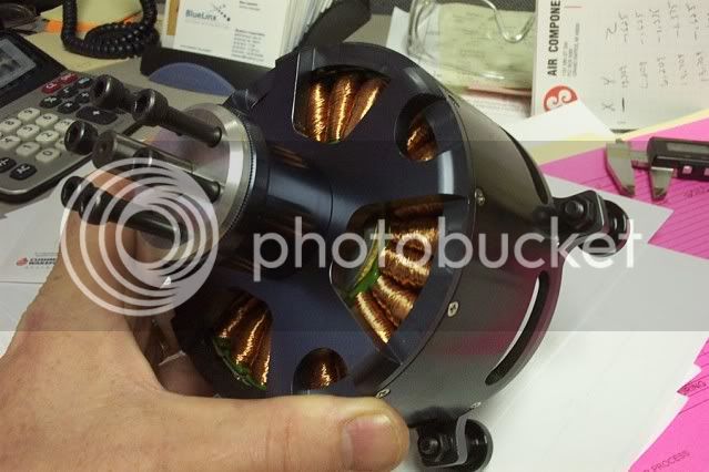
Also please upload some pics, if you have any...
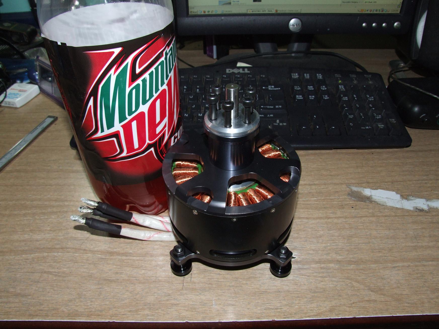
The part that sticks out of the front is 10mm. The rear, however, is a 12mm. I have yet to take the motor completely apart, but I guess at some point it reduces.
I threw it on a 100A Turnigy controller that I had sitting around.