Hello all!
I woul like to share my long journey with you, briefly about the construction of my charging device.
The story begins with countless battery drains, always in some impossible place. We usually go on trips with children and a trailer, and during one of our adventures I had to prop the dead vehicle against a car charging post. That's when I came up with the idea to buy a converter so that I could not just charge the machine from an outlet. This was about two years ago, and since then I have carried this prototype in my bag and charged it many times.
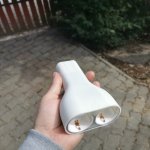
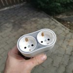
Pictures of the current product
It turned out that we once had a waffle maker, and we baked dough and a filling while the machine was charging. Since then, this has become a tradition and we take it with us when we go far. But this entailed the need for a distribution head, which is again large and bulky.
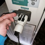
Picture of the first proto.
So I figured out that I needed a charger with two outputs, simple, small and light. Which I always have. And I built one. Another one for my wife. Another one for my friend. And so on until they asked, why don't I sell these?
I wrote a little about it in the topic for sale, check it out.
But then the presentation of the project should follow.
The charging head is 143mm long and weighs 235g. It's quite small and compact. Requests 13A from the column based on its current setting. That's enough for everything I've needed so far.
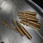
Picture of the connectors.
You can't buy a connector anywhere, so I thought it's no problem, I'll make a couple. I manufactured them exactly according to the factory specifications. Later, they also receive a galvanic coating, but they still work flawlessly.
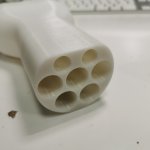
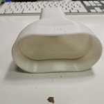
Picture of the cover.
In order to achieve the compact size, it was necessary to design and manufacture our own enclosure. I tried several methods for this, SLA and FDM printing. Both were only needed for prototyping, but after a lot of use, FDM PETG worked so well that I went with it.
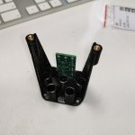
Image of the inner holder
When designing the interior, I aimed for very easy assembly, compactness and touch protection. Even though it is not rainproof because the cover is not sealed, it can withstand a downpour surprisingly well. But I don't recommend using it in the rain.
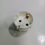
Picture of the Legrand housing
For the network connector, I was looking for a connector with contact protection and proper grounding. The interior of the Legrand swing connector was the smallest, so it was the winner.
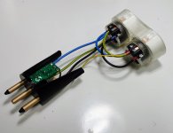
Picture of the assembled interior.
I definitely wanted to put the electronics on a PCB, but before I could design it, I found a free-to-use, well-documented project on git (link), which was suitably small and had many functions, and it fit right here.
I connected the wiring with 2sqmm wires to make sure it's over designed, although you won't get more than 13A from the pole. The ends of the wires are crimped because that's how it fits.
Despite the fact that I work as a product design engineer, it was a good weekend to plan and implement this. It has gotten me out of trouble quite a few times, when I didn't even remember I had it with me. I hope you enjoyed the story too. If you have any questions, I'm here.
I woul like to share my long journey with you, briefly about the construction of my charging device.
The story begins with countless battery drains, always in some impossible place. We usually go on trips with children and a trailer, and during one of our adventures I had to prop the dead vehicle against a car charging post. That's when I came up with the idea to buy a converter so that I could not just charge the machine from an outlet. This was about two years ago, and since then I have carried this prototype in my bag and charged it many times.


Pictures of the current product
It turned out that we once had a waffle maker, and we baked dough and a filling while the machine was charging. Since then, this has become a tradition and we take it with us when we go far. But this entailed the need for a distribution head, which is again large and bulky.

Picture of the first proto.
So I figured out that I needed a charger with two outputs, simple, small and light. Which I always have. And I built one. Another one for my wife. Another one for my friend. And so on until they asked, why don't I sell these?
I wrote a little about it in the topic for sale, check it out.
But then the presentation of the project should follow.
The charging head is 143mm long and weighs 235g. It's quite small and compact. Requests 13A from the column based on its current setting. That's enough for everything I've needed so far.

Picture of the connectors.
You can't buy a connector anywhere, so I thought it's no problem, I'll make a couple. I manufactured them exactly according to the factory specifications. Later, they also receive a galvanic coating, but they still work flawlessly.


Picture of the cover.
In order to achieve the compact size, it was necessary to design and manufacture our own enclosure. I tried several methods for this, SLA and FDM printing. Both were only needed for prototyping, but after a lot of use, FDM PETG worked so well that I went with it.

Image of the inner holder
When designing the interior, I aimed for very easy assembly, compactness and touch protection. Even though it is not rainproof because the cover is not sealed, it can withstand a downpour surprisingly well. But I don't recommend using it in the rain.

Picture of the Legrand housing
For the network connector, I was looking for a connector with contact protection and proper grounding. The interior of the Legrand swing connector was the smallest, so it was the winner.

Picture of the assembled interior.
I definitely wanted to put the electronics on a PCB, but before I could design it, I found a free-to-use, well-documented project on git (link), which was suitably small and had many functions, and it fit right here.
I connected the wiring with 2sqmm wires to make sure it's over designed, although you won't get more than 13A from the pole. The ends of the wires are crimped because that's how it fits.
Despite the fact that I work as a product design engineer, it was a good weekend to plan and implement this. It has gotten me out of trouble quite a few times, when I didn't even remember I had it with me. I hope you enjoyed the story too. If you have any questions, I'm here.

