Version 2 Crystalyte Controller information

calinb said:
The old schematic shows a 2N5551 for the NPN side. Is this part okay, fecter?

http://search.digikey.com/scripts/DkSearch/dksus.dll?Detail?name=MMBT5551FSCT-ND

Thanks,

-Cal

That looks like it should work fine.
 
monster said:
i used 4110's as that was what was in my controller origionally.
Then they should work for me too. I bet I still have something fried on my board. More ohm meter work!
 
Was just told some useful info, you can use capacitors in series, so can use two 100v caps in series as a 200v cap,
might be useful to someone
 
seems puting caps in series also lowers the total uF rating two 100v caps 1000uF in series gives 200v 500uF equivalent
 
calinb said:
fechter said:
The old schematic shows a 2N5551 for the NPN side. Is this part okay, fecter?

http://search.digikey.com/scripts/DkSearch/dksus.dll?Detail?name=MMBT5551FSCT-ND

I finally ordered the transistors from DigiKey. Great company! They charged me only for actual U.S. Postal postage. I didn't think any mail order stores did that any longer because they can skim additional profit in "handling" charges.

After replacing both the PNP and NPN transistors with the above parts, my controller works. :) It was a waste of my time trying to cross the parts to locally available transistors.

Thanks for your help, Fecter, and thanks to Monster for verifying his Ver. 2 board had 4110s in it. I replaced all six of my 4310s with 4110s. I'd populate the other six FET locations too, but I'd first like to know if that's all that I need to do to get it working with the full complement of twelve FETs.

-Cal
 
Notes on Using REGEN on Crystalyte CT4840 v2 Controller.

This assumes you are using the standard three-wire levers that cut out the cruise control.

All you need to do is wire from ABS to the GROUND pads on the board. Put a switch in the wire to enable/disable regeneration. When either brake is pulled, the controller goes into regeneration. The switch can be thrown at any time and DOES NOT need to be engaged at power up.

I had trouble with the standard torque arm. Care must be taken that there is NO slop in the connection and the arm is tight against the fork. My arm worked great under tension but had trouble handling reverse torque under braking. My fork dropouts spread a little (there may have been a little slop there too) and the torque arm seems to have rounded out a bit. I ordered a new fork, new C'lyte torque arm and another torque arm from high-power cycles. There appears to be something coming from Ampedbikes (see the torque arm thread on this forum) that I will also explore.

Anybody have any ideas on how to either adjust the braking response (level or ramp-up) or make it adjust by brake pressure with a pot?
 
greasypants said:
Managed to get the controller working - two of the mosfet insulating washers needed to be replaced.

Here are the controller codes from Justin if anyone needs them.

V2 Controller Indicator Status Instruction

 Indicator light off: Normal working
 Indicator light on: EABS braking status
 Indicator light on for 0.5 second - flash 1 time - off for 1 second: Standby status
 Indicator light on for 0.5 second - flash 2 times – off for 1 second: Brake signal
 Indicator light on for 0.5 second - flash 3 times – off for 1 second: MOS damage
 Indicator light on for 0.5 second - flash 4 times – off for 1 second: Immediate start at high speed protection
 Indicator light on for 0.5 second - flash 5 times – off for 1 second: Electric current failure
 Indicator light on for 0.5 second - flash 6 times – off for 1 second: Power supply’s low voltage protection
 Indicator light on for 0.5 second - flash 7 times – off for 1 second: Hall effect signal failure
 Indicator light on for 0.5 second - flash 8 times – off for 1 second: No throttle signal
This may be a silly question, but why is the Status Indicator LED mounted inside, on the PC board, when most of the flash codes refer to external conditions :roll: I think it would be better mounted near the switch, on the end plate. It just seems a waste to open the controller to find the problem is external :x

Blessings, Snow Crow
:roll: :roll:
 
Just doing some tests with v2 and x5303 on 86volt, it looks like the v2 might have a 60v cut off for regen, other controllers designed for 48v use a 60v cut off for regen to protect sealed lead acid batteries from overcharging, so if motor produces over 60volt when in regen mode the regen cuts off, if battery voltage is down it pulls down the regen voltage down, so only get over 60v when batteries are full ( and possibly if going very fast when regen applied).
Anyway looks like no regen over 48v on v2, I suspect might be able to adjust the cut off level via a resistor value, but which resistor no idea unfortunately, anyone out there got any ideas.
One idea I have is to put motor in reverse when wanting to brake ( if using over 48v), I'll do some low load tests first and see what happens. If anyone has tried or if there is some danger of blowing some fets by hitting reverse when moving forward will give the experiment a miss.
 
solarbbq2003 said:
One idea I have is to put motor in reverse when wanting to brake ( if using over 48v), I'll do some low load tests first and see what happens. If anyone has tried or if there is some danger of blowing some fets by hitting reverse when moving forward will give the experiment a miss.

I don't think that's a good idea.

I've done it by accident a few time with my bench test setup.
Not only will you be using battery power (and lots of it) to slow down the motor, you'll also be exposing the FETs to the worst possible overload.

There may be a way to reconfigure the hall sensors to get a regen that works. Sort of like vector control. I don't know if this would work though. It would also be somewhat complex to switch.
 
just tested puting x5303 in reverse when motor running forwards, the controller wont recognise reverse function until wheel stops spinning, so no good for using reverse as regen, same works other way, if wheel going backwards and disengage reverse, forward wont start until wheel stops spinning backwards.....clever controller!!
 
probably lucky it didn't work, just read your post fechter after I did test!!! lucky
pretty sure there will be some way the chip is recognising when 60volt is reach and turning off regen function, guessing will be a matter of changing resistor value so that chip will keep regen function on over 60v, thats my guess anyhow
 
thats a good idea to use the halls and thick phase wires, still not sure if the fets will like it, just requires swap two hall wire and two phase wire positions to run in reverse ( not using controller reverse function), still I would be a bit worried about what is going to happen to the fets, I assume if I run reverse by hall and phase wire switching i'll end up in situation you desribe fechter, might be best if dont try that one. think best solution will be trying to figure out how chip is recognising 60v, that will be tricky
 
big mistake guys and gals, regen does work at 86volt!! my mistake I didn't have the wire for abs connected, whoops!
I'll test what voltage it produces if its going to be too high for the fets,
also something quite odd: after power turned off if measure voltage across positive and negative wires ( positive batt terminal not connected to batteries), there is a voltage being giving out by controller starts about 17volts and slowly rises even though no power being applied to controller, only watched it for a few minutes but it was rising, guessing something to do with the caps, no idea really.
but happy to report there is no 60v cut off on the regen seems to be ok on higher voltages.
 
regen on 86volt with v2
seems to work fine no load conditions, wheel off the ground, was a little delay before regen kicked in, not immediate, but only a small delay . Measured voltage of pack at start was 82.4 volt ( cobalt lithiums( 30ahr), not fully charged, fully charged is up around 86volt), motor was x5303 , no load max rpm with v2 was 978rpm ( measured with hand held dig. tacho), at max rpm battery voltage was 80.8volt, current drawn by x5 at no load was 6amps ( quite large).
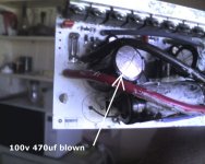
When regen was engaged at max rpm, volts went up to 85volts ( good news no where near 100v max of the 4110 fets), though pack was not fully charged would expect a bit higher with fully charged pack, max amps back into batts ( very briefly was 16amps).
Appeared regen not working when did a road test, has anyone else had issues with the regen on v2? I might just have a bad connection somewhere.
 
just something might be of interest on flat road with v2 controller, 86v 35amp x5303 motor getting a bit over 50km/hr in 26" rim, slightdownhill will get up near 60km/hr ( its a three wheel vehicle quite a bit heavier than a pushbike) has a fairing/windscreen. I was expecting top speed on 35amp to be a bit higher than that.
 
at 82.4volt no load rpm of 978rpm in 26" rim equates to 121km/hr with v2
At 35amp with my 3 wheeler at 82volt getting a bit over 50km/hr in 26" rim on flat road with fairing, I can see why a huge amount of amps needed to get high speeds with x5.
 
I just got my Cycle Analyst from oat.net (great deal - check out the selling and surplus area; he may still have some) but I can't seem to find anything that says where to wire it onto my controller (Yes, I tried the search function). It's the Crystalyte CT4840 controller - the V2, I believe. The board has RFW4850-V06 07-05-11on it. Everything I saw here has the green board, mine is white. eBikes doesn't have anything on their site that I can find. HELP!
 
Have been testing x5303 running on 86volt 35amp v2 controller, doing some road testing in three wheeled vehicle a bit heavier than standard bike, it has fairing. Top speed with wind behind trike and slight downhill was 79km/hr.
After reaching top speed starting going up a hill and got controller failure with obvious capacitor failure with lots of smoke, speed at time of failure was quite low maybe 15-20km/hr but under high load hill a bit steep.
Closer inspection showed:
1. the section of board that takes the high amp current along a track had blown ( I hadn't added a shunt wire to avoid that track will certainly be adding one)
2. track on circuit board going to big cap ( 100v 470uF) near fets turned brown had got hot ( will probably need beefing that up a bit also)
3. probably mosfet failure when high amp track has blown ( 4110 fets)
So I think you can probably say the v2 board as it comes from crystalyte is not going to handle 86v 35amp with x5 motor unless some mods are made. 86volt is fully charged 72volt lithium cobalt system. Shunt definitely needed to avoid high amp track on v2 board, possibly also higher voltage caps and higher uf caps needed also, but not sure if my capacitor failure might have been due to the high amp track on board failing.
86v35am79kmhr1.jpg
View attachment 1
 

Attachments

  • 86v35am79kmhr2.jpg
    86v35am79kmhr2.jpg
    65.5 KB · Views: 2,620
found cause of failure, cap at bottom of pic above, my solder had broken, without that cap the 470uF blew, and probably then caused fets to blow, 2 fets damaged on middle phase, one high side one low side
 
solarbbq2003 said:
at 82.4volt no load rpm of 978rpm in 26" rim equates to 121km/hr with v2

At 35amp with my 3 wheeler at 82volt getting a bit over 50km/hr in 26" rim on flat road with fairing,

Have been testing x5303 running on 86volt 35amp v2 controller, Top speed with wind behind trike and slight downhill was 79km/hr.

86volt is fully charged 72volt lithium cobalt system

Some comments:
a) It seems that your 3 wheeler is of 26" rim!?

b)If so, at 50kmh top speed on flat (about 41% of no-load speed), the 3 wheeler is limited by the battery current limit of 35A.
The motor current could be about 2.4 times of the battery current (about 85 A).
And it will cause an high current ripple in these 100V capacitors (order of 85A)

c) If so, at 79kmh top speed on slightly downhill ( about 65% of no-load speed), the 3 wheeler is also limited by the battery current limit of 35A.
The motor current could be about 1.5 times the battery current (about 53A).
And it will cause an high current ripple in these 100V capacitors (order of 53A).

d) These high motor current and high current ripple will damage the weak tracks on the pcb board.

e) IMO. The damaged tracks caused open-circuit and the induced high voltage spikes (due to the motor inductance) damaged the FETs.
 
thanks for that , on this occasion when i looked at caps, it seems my dodgey soldering has come apart on one cap ( not related to temp or anything i think just vibration and a bad solder has started the failure process.
But you've brought up the interesting point of motor current can be higher than battery current, something I only recently became aware of, can you go further into how thats possible?
 
solarbbq2003 said:
But you've brought up the interesting point of motor current can be higher than battery current, something I only recently became aware of, can you go further into how thats possible?

Let us use an simple circuit for illustration.
.
The motor is simplified as an L and R as shown in the circuit B.
The switch SW is closed for X% in an period (duty cycle of X%) at the PWM frequency.

When the switch is closed, current I2 = current I1.
When the switch is open, I1=0.
But I2 is NOT zero and continues to flow in an decaying manner due to the inductance L through the freewheel diode D.

So the average value of the motor current I2 is greater than the average value of the battery current I1 over an period.

Hope this will be of some help.
 

Attachments

  • 01-08-07_2217 copy.jpg
    01-08-07_2217 copy.jpg
    16.9 KB · Views: 2,469
Back
Top