
But you could use external reduction gear to make it a great hill climber at half of that speed.docnjoj said:Hey Brett1 Who wants to go 50 mph on an Ebike?
otherDoc
You are using an out of date browser. It may not display this or other websites correctly.
You should upgrade or use an alternative browser.
You should upgrade or use an alternative browser.
Version 2 Crystalyte Controller information
- Thread starter rsisson
- Start date
docnjoj
1 GW
Yeah The7! But you're are talking double reduction on a hub! Gotta be an easier way to climb a hill!
otherdoc
otherdoc
solarbbq2003
10 kW
- Joined
- Apr 7, 2007
- Messages
- 500
I'll try going higher voltages and see what happens, the 3,300rpm figure was just a number given by a translator who knows nothing on technical side of controllers, so I would take it with a pinch of salt, but thats very interesting that there are limits to iron core type motors at higher frequencies
using dsp switch: reverse is 1152rpm
interesting: no load forward is 2.3amps, very high really ( maybe i have forward direction wrong) maybe the gears using up some amps, mayb hall sensor board not in correct position, can lower amps a bit moving the hall sensor board)
no load reverse about 1amp
To run the circuits from a separate power supply to the fets, say just run the board on 24v battery, where would I connect the negative wire to?? can do some higher voltage tests then without worrying too much about damaging the low volt circuits
to doc: 50mph?? think we can go better than that!!
2.3 A is very reasonable for no-load 2389 rpm (637 Hz) due to high iron loss and moderate mechanical loss.solarbbq2003 said:interesting: no load forward is 2.3amps, very high really ( maybe i have forward direction wrong) maybe the gears using up some amps, mayb hall sensor board not in correct position, can lower amps a bit moving the hall sensor board)
It could be seen on the scope of Fechter and Jozzer that there is an phase advance of about 20deg in the applied phase voltage (with respect to BEMF) in the PUMA/BMC. This 20 deg advance was further verified by me when viewing the Hall sensor location in the PUMA rotor.
This 20 deg advance might have increased the motor current by about 6% due to the power factor of 0.94 (cosine 20 deg = 0.94). This assumes the BLDC motor acts similar to an 3-phase motor.
IMO. Since PMUA is only working in one direction, the Hall sensors should be placed without any advance because this is the best theorectical loaction. To compensate the inductance, a slight advance of no more than 5 deg seems to be optimal.
Note that my AL1020 motor takes 1.9A at an no-load top speed of 61km/h (about 540Hz) using 48V battery. Al1020 motor is also an geared hub but with lower power output than Puma/BMC. There is no phase advance in AL1020.
solarbbq2003 said:using dsp switch: reverse is 1152rpm
no load reverse about 1amp
1152 rpm (reverse) is approximately half of 2389 rpm (forward).
It does show that V2 has been designed with a lower reverse speed when using dsp switch.
However, the exact ratio should be tested with Crystalyte motors.
The negative of the 24 battery should be connected to the negative of the power supply.solarbbq2003 said:To run the circuits from a separate power supply to the fets, say just run the board on 24v battery, where would I connect the negative wire to??
Should not be a problem if it is not higher than 72 V and running for no more than a few minutes.solarbbq2003 said:can do some higher voltage tests then without worrying too much about damaging the low volt circuits
solarbbq2003
10 kW
- Joined
- Apr 7, 2007
- Messages
- 500
I'll work out wiring for other direction and see what no load is, sensors are place not in centre of the coil poles, pretty sure I have it running backwards.
With running the board on separate power supply I mean physically on the board where would I connect negative battery terminal to? there are a couple of earth pins where the throttle/hall sensors etc connect to...?
I've only got 63v big caps on this controller at the mo, hence a bit worried about going to higher voltages, might wait till I get some 100v caps in. Just in case.
So in theory a hallbach array type motor with no iron core could go to higher rpm without same losses as an iron core motor??
rkosiorek
100 kW
The7 said:solarbbq2003 said:using dsp switch: reverse is 1152rpm
no load reverse about 1amp
1152 rpm (reverse) is approximately half of 2389 rpm (forward).
It does show that V2 has been designed with a lower reverse speed when using dsp switch.
However, the exact ratio should be tested with Crystalyte motors.
Thanks Brett for confirming that the V2 controller is designed or programmed with the "REVERSE" speed limited to approximately Half of the Forward speed. for all practical purposes this means that one cannot use the reverse switch the same way as with the old V1 controller.
rick
solarbbq2003 said:I'll work out wiring for other direction and see what no load is, sensors are place not in centre of the coil poles, pretty sure I have it running backwards.
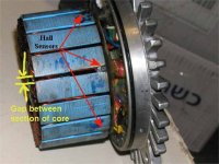
The location of Hall sensors as seen on the gearless BMC motor (from Fechter) are at the gaps between the coil poles. At such location, it will give an 20 deg phase advance as expected.
I have not seen the exact location of the Hall sensors for an geared hub PUMA/BMC motor. Wonder if an pic of it could be posted.
Attachments
It's basically the same arrangement only with twice as many poles.

Connect the battery negative to the negative terminal of the separate power supply.solarbbq2003 said:With running the board on separate power supply I mean physically on the board where would I connect negative battery terminal to? there are a couple of earth pins where the throttle/hall sensors etc connect to...?
Sounds right. But there are still iron paths for the magnetised flux.solarbbq2003 said:So in theory a hallbach array type motor with no iron core could go to higher rpm without same losses as an iron core motor??
calinb
100 W
- Joined
- Oct 28, 2007
- Messages
- 102
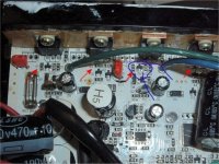
The FET control has definitely changed in Ver. 2. I think the pinout of the MMBT5401 might not work. The lone "center" pin of the SMD transistor package is connected to the gate of the FET. This should be the PNP emitter. The lower right pin of the SMD transistor is connected to the source lead of the FET so this should be the PNP collector. Thus, the collector and emitter pins appear to be swapped, compared to the MMBT5401fechter said:OK, T5 looks like a PNP high side driver. On the analog controller, this is a 2n5401.
The surface mount version of this is a MMBT5401: http://www.fairchildsemi.com/ds/MM/MMBT5401.pdf
You can get it from DigiKey: http://search.digikey.com/scripts/DkSearch/dksus.dll?Detail?name=MMBT5401FSCT-ND $0.14ea.
There's also a 2nd BHD 1F transistor in the circuit (also with BHD 1F markings). I haven't attempted to create a schematic. It's blown on my board too--along with the BJD 1I transistor so I need to replace all three of them.
I could just buy some 2N5551 and 2N5401 transistors in a TO-92 package and solder them to the board's SMD device pads. An NTE288 crosses to the 2N5401 and an NTE194 crosses to the 2N5551. They are available locally.
Has anyone managed to successfully replace any of the gate transistors and get their controller working again?
Thanks,
-Cal
solarbbq2003
10 kW
- Joined
- Apr 7, 2007
- Messages
- 500
i get different location for sensors on motors i've come across for geared mbc
rkosiorek
100 kW
the locations of the Hall Sensors in the 2 BMC geared motors i have diassembled are identical to that in the photo posted by Brett. they are not in the slot but instead are over the edge of the coil.
i wonder which location giveds the best performance? centered in the slot or over the edge of the coil?
rick
i wonder which location giveds the best performance? centered in the slot or over the edge of the coil?
rick
rkosiorek said:the locations of the Hall Sensors in the 2 BMC geared motors i have diassembled are identical to that in the photo posted by Brett. they are not in the slot but instead are over the edge of the coil.
i wonder which location giveds the best performance? centered in the slot or over the edge of the coil?
rick
See my comment on:
Hall Senor Location in PUMA/BMC motors
http://endless-sphere.com/forums/viewtopic.php?f=2&t=4996
Wonder if you could check whether the centre of the Hall sensor is in line with the centre of the coil pole?
dirty_d
10 kW
one thing im curious about, how does the magnetic field from the stator teeth not interfere with the hall sensors? as far as spacing, i don't think it matters if they are exactly in the center of a stator pole or exactly between two stator poles as long as they are separated by 120 electrical degrees. changing the location between the two would just require the wiring to be changed, but it would still be neutrally timed.
Please read the posts:dirty_d said:one thing im curious about, how does the magnetic field from the stator teeth not interfere with the hall sensors? as far as spacing, i don't think it matters if they are exactly in the center of a stator pole or exactly between two stator poles as long as they are separated by 120 electrical degrees. changing the location between the two would just require the wiring to be changed, but it would still be neutrally timed.
Hall Senor Location in PUMA/BMC motors
http://endless-sphere.com/forums/viewtopic.php?f=2&t=4996
BEMF and Hall signals
http://endless-sphere.com/forums/viewtopic.php?f=2&t=4528
Asymmetrical voltage in Puma. Why?
http://endless-sphere.com/forums/viewtopic.php?f=2&t=4542
solarbbq2003
10 kW
- Joined
- Apr 7, 2007
- Messages
- 500
the7: you've been busy!!!great info
the black dotted line in pic i put up of bmc shows location of the centre hall pin on stator pole, I'll do a test when get time measure rpm and no load amps of board in different locations, a load test would be good but not set up to give same load each time I do the test. But having board located as in previous posted pic direction of rotation would make a difference on how motor performs.
with regards to connecting up separate low voltage power supply for the board, would the connect as shown in the pic below work? ( the battery symbol in pic i might have it back to front but I put a plus and minus sign to clarify).
solarbbq2003 said:with regards to connecting up separate low voltage power supply for the board, would the connect as shown in the pic below work? ( the battery symbol in pic i might have it back to front but I put a plus and minus sign to clarify).
(Yes. The battery symbol is back to front.)
I do not have the board in hand and am unable to confirm the exact points of connection on board.
If you use a separate low voltage power supply for the board, you have to isolate the high voltage power supply to this part of the board.
The isolation of the high voltage power supply may mean desoldering one leg of a series resistor.
For the location of the Hall sensor as marked, I have to re-determine the advance of the phase voltage.
Please see:
Hall Senor Location in PUMA/BMC motors
http://endless-sphere.com/forums/viewtopic.php?f=2&t=4996
solarbbq2003
10 kW
- Joined
- Apr 7, 2007
- Messages
- 500
location of sensor
solarbbq2003
10 kW
- Joined
- Apr 7, 2007
- Messages
- 500
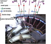
pic trying to show what happens as sensor location is moved, the point in middle of stator poles just on either side get reversal in motor direction, sweet spots where motor runs smooth and quiet shown, where fechters pic has hall sensor, just on either side of the middle motor will run but is a quick direction change just on either side of the middle, but motor not running as well as on the sweet spots. Very noticeable when your on the sweet spot, motor runs optimally, can hear some noise in motor and change in rpm and amps if not on sweet spots.
I am greatly impressed by your experiments.solarbbq2003 said:pic trying to show what happens as sensor location is moved, the point in middle of stator poles just on either side get reversal in motor direction, sweet spots where motor runs smooth and quiet shown, where fechters pic has hall sensor, just on either side of the middle motor will run but is a quick direction change just on either side of the middle, but motor not running as well as on the sweet spots. Very noticeable when your on the sweet spot, motor runs optimally, can hear some noise in motor and change in rpm and amps if not on sweet spots.
Wonder if you have noted down the rpms and battery currents at the various marked positons A,B,C,D,E,F,G,H,I,J,K,L,M,N and O.?
If not, wonder if you could do it again at 36V power supply with current limiting of 2 to 3A.
It is a pity that you do not have an scope to show the phase voltage waveforms at these positions to see the phase advance (leading) and retard (lagging) of the applied voltage wrt the BEMF.
Several comments as noted from the picture:
1) CCW sweet point at C is the nominal position for your BMC !?
The best theorectical postion is at B.
Perhaps with a slight advance of 5 deg from B is an optimum point to compensate the inductance of the motor.
However, it will have an advance of about 26 deg at C.
2) The second CCW sweet point is at K. Why?
I would expect that the second CCW sweet point is at position "O" ! ( I think that my expection could be wrong and more research/thinking is needed)
3) From C to D: the advance of the phase voltage will increase the speed.
4) D is a VERY critical point at which the rotation change in direction when the speed is the HIGH.
It seems that position D is the nominal position for Fechter's PUMA! Why? ? ? ? ?
Wonder if Solarbbq2003 could do an experiment to find if D could be used as an operating position?
Move the Hall sensor at D, and try to find the best combination of ( phase and Hall) connections for CCW.
If the best combination exists, it would have the identical performance as Fechter's PUMA.
I think that it exists.
5) H is a critical point (not as critical as D) at which the rotation change in direction when the speed is LOW.
Perhaps Fechter's PUMA chooses H instead of D as the nominal postion.
6) L is as critical as D.
Attachments
dirty_d
10 kW
oops
dirty_d
10 kW
is it possible that the sweet spot being off center is due to the fact that the MCU on the controller has a slight delay, so if the hall sensors are in the center the commutation doesn't happen until after the magnets pass the point where the next commutation step should have occured? by placing them off center it would make up for the delay. just a theory.
guessing that the diameter rotor where the magnets are is 10", at 300rpm the magnets move 1" in 6 milliseconds, the hall sensor looks like its about 1/8" off center, so it takes 750 microseconds for the magnets to move 1/8", 750 microseconds seems like a long long time for an MCU, so maybe this isn't the reason for the off center sweet spot.
guessing that the diameter rotor where the magnets are is 10", at 300rpm the magnets move 1" in 6 milliseconds, the hall sensor looks like its about 1/8" off center, so it takes 750 microseconds for the magnets to move 1/8", 750 microseconds seems like a long long time for an MCU, so maybe this isn't the reason for the off center sweet spot.
dirty_d said:is it possible that the sweet spot being off center is due to the fact that the MCU on the controller has a slight delay, so if the hall sensors are in the center the commutation doesn't happen until after the magnets pass the point where the next commutation step should have occured? by placing them off center it would make up for the delay. just a theory.
guessing that the diameter rotor where the magnets are is 10", at 300rpm the magnets move 1" in 6 milliseconds, the hall sensor looks like its about 1/8" off center, so it takes 750 microseconds for the magnets to move 1/8", 750 microseconds seems like a long long time for an MCU, so maybe this isn't the reason for the off center sweet spot.
You did answer your own question.
monster
100 kW
- Joined
- Jun 17, 2007
- Messages
- 1,411
calinb said:The FET control has definitely changed in Ver. 2. I think the pinout of the MMBT5401 might not work. The lone "center" pin of the SMD transistor package is connected to the gate of the FET. This should be the PNP emitter. The lower right pin of the SMD transistor is connected to the source lead of the FET so this should be the PNP collector. Thus, the collector and emitter pins appear to be swapped, compared to the MMBT5401fechter said:OK, T5 looks like a PNP high side driver. On the analog controller, this is a 2n5401.
The surface mount version of this is a MMBT5401: http://www.fairchildsemi.com/ds/MM/MMBT5401.pdf
You can get it from DigiKey: http://search.digikey.com/scripts/DkSearch/dksus.dll?Detail?name=MMBT5401FSCT-ND $0.14ea.
There's also a 2nd BHD 1F transistor in the circuit (also with BHD 1F markings). I haven't attempted to create a schematic. It's blown on my board too--along with the BJD 1I transistor so I need to replace all three of them.
I could just buy some 2N5551 and 2N5401 transistors in a TO-92 package and solder them to the board's SMD device pads. An NTE288 crosses to the 2N5401 and an NTE194 crosses to the 2N5551. They are available locally.
Has anyone managed to successfully replace any of the gate transistors and get their controller working again?
Thanks,
-Cal
dude i am just about to solder my board back together and now you say that!
 what should i do for T5? your advice clashes with fechters. can we resolve this so i don't have to make a 50/50 guess :? cheers
Attachments
Similar threads
- Replies
- 25
- Views
- 4,249
- Replies
- 14
- Views
- 1,615
- Replies
- 7
- Views
- 2,518
- Replies
- 4
- Views
- 492
- Replies
- 13
- Views
- 1,137