Voicecoils's 2nd build: Giant DH Team

VC, call the guys who are building your pack. if they haven't welded it yet you can get them to assemble it to fit into the frame like deec did on his build, that was so sweet, using the water bottle and pump studs, they will weld it up however you ask them, if you send them a cardboard outline, they could do it very accurately i would expect, for no more cost. do it like deec did.
 
lawsonuw said:
How about going with a "half-cross" pattern? (just made this up) If the position of the spokes that I've circled in red were swapped the spokes wouldn't be angled as much. Going with a mixed pattern is another idea I just had. Mix in 6 evenly spaced radial spokes per-side to take road loads, while the remaining 6 pairs of 1-cross spokes transfer the motor's torque. (a 10 radial and 4-pair of 1-cross, or 12 radial and 3-pair of 1-cross might also work)

My 2 electron volts,
Marty

Thanks for the exemple, What i decided with this choice of spoke crossing is for big torque on the wheel... i've calculated that at 100V and 90A, the torque on the tire would be like 150lbs so the spokes need to be angled to reduce the mecanical stress on the spoke tension.
 
voicecoils said:
Doctorbass said:
I used the 24" rim and spokes that justin sold me. that was heavy 12 gauge spokes. I had a problem cause the nipples did not fit corectly in the holes, so i needed to drill them. Also, the spokes was a bit short! i would have had like 3mm more long spokes. see the pic

Thanks Doctorbass, do you know what the spoke length was? I have calculated 138mm but perhaps I should add a few mm for dishing.

I am not sure that thick spoke = strong spoke. Spokes almost always fail at the head or nipple, not in the middle. I'm thinking maybe a 13ga/14ga butted spoke may even be suitable.

Can you tell me how many gears are in your cassette and how you went with dropout spacing? Or a link to your build maybe :D

Cheers! I can't wait to get mine running.

I have 7 gear in the cassette and Justin is supposed to send me a 11tooth to replace my 14 tooth.

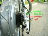
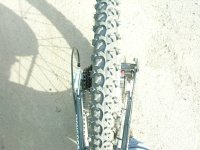
Here is some pics of the spacing of my dropout, frame torque arm and diskbrake.
 

Attachments

  • description2.JPG
    description2.JPG
    112.4 KB · Views: 2,895
  • P1040288_800x600.jpg
    P1040288_800x600.jpg
    41.8 KB · Views: 2,928
  • DSCN4712_800x600.jpg
    DSCN4712_800x600.jpg
    84.7 KB · Views: 2,932
dnmun said:
VC, call the guys who are building your pack. if they haven't welded it yet you can get them to assemble it to fit into the frame like deec did on his build, that was so sweet, using the water bottle and pump studs, they will weld it up however you ask them, if you send them a cardboard outline, they could do it very accurately i would expect, for no more cost. do it like deec did.

If you read a few posts back you'll see packs have been received already. tab welded into two bricks of 2 x 6 cells each. (36v 10ah nominal each)

Fortunately they already fit in the frame as is. Just a matter of packaging/protecting them and sorting out attachment to the frame.
 
Doctorbass said:
Here is some pics of the spacing of my dropout, frame torque arm and diskbrake.

Great pics thanks!

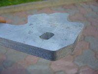
Tell me about your torque arms. They look like laser cut.

I was thinking about laser cut stainless steel, 5mm thick. What do you think?

Oh and do you know your spoke lenght? Sorry to keep asking!
 
voicecoils said:
Doctorbass said:
Here is some pics of the spacing of my dropout, frame torque arm and diskbrake.

Great pics thanks!

Tell me about your torque arms. They look like laser cut.

I was thinking about laser cut stainless steel, 5mm thick. What do you think?

Oh and do you know your spoke lenght? Sorry to keep asking!

That's 9mm thick alluminium on each torque arms. they was cuted with a CNC.

I dont remember the spokes lenght. i'll ask to Justin for that.
 
I would recommend against anything exotic on lacing. A standard 1 cross or radial should be fine, with quality 14 guage spokes. Mixing radial and 1 cross is not a good idea unless the dish of the wheel is extreme.

The pictured suggestion of Marty will not work, as each hole in the rim is offset to one side or another (or angled) on almost all rims. If you move the spoke one hole over, it will be laced to the wrong side of the rim.

It looks like 1x is the limit for a 26" build with your motor, and a 24" rim needs modification or a radial lace. With such short spoke lengths you won't notice too much flex in a radial lace honestly.
 
voicecoils said:
Doctorbass said:
Hey Voicecoils,

I really think you should consider this way of placing your battery. this allow you a very good handling and lower the center of gravity. Believe me, that help!
Doc

I agree there may be some advantages to you're proposed placement of batteries. Cruisers have low weight while super motos / dirt bikes have the weight more centralised and higher up. So perhaps it depends on the sort of riding your after.

I think with my proposed battery placement the battery weight is a bit high and and towards the back of the bike compared with the KTM pictured above. However, it will be much easier to mount in that position and be more stealth. 8)

If it does feel really bad, I'll look to the option you've draw up. Maybe a super long distance pack 8)

Cheers!

Hi,

It might be a good idea to make up a couple of cloth sacks filled with sand (use the legs from a worn out pair of pants) that each weigh about as much as one of your battery packs. Then try riding your bike with the sacks in tied in the different possible positions (you might want to pay attention to how subject the locations are to wheelies). This way you will be absolutely sure you are making the choice you prefer. This will be much easier than changing the mounting location later if it turns out to ride badly with your first choice.
 
Doctorbass said:
That's 9mm thick alluminium on each torque arms. they was cuted with a CNC.

Thanks Doc, the torque arms look great :D
Would you be willing to share the CAD file for them? (.DFX?)

I may have to get some laser cut, and want to make sure I've got the threaded radius and flat sections right.
 
johnrobholmes said:
I would recommend against anything exotic on lacing. A standard 1 cross or radial should be fine, with quality 14 guage spokes. Mixing radial and 1 cross is not a good idea unless the dish of the wheel is extreme.

It looks like 1x is the limit for a 26" build with your motor, and a 24" rim needs modification or a radial lace. With such short spoke lengths you won't notice too much flex in a radial lace honestly.

Thanks. I may try for a butted spoke then with 13ga towards the head and 14ga along the length, in a 1 cross.

From ebike.ca one cross looks do-able and the dishing is not crazy. At first glance it seems a bit extreme but the hub flanges are actually offset which is why the 5304 has a bit extra junk in the trunk on the LHS.
M5304R26.jpg


My rim does not have any hole offsets or angled holes, but the nipple holes would have to be filed or dremeled out for bigger nipples. I tried seating the 12ga nipples they're far to big.
 
MitchJi said:
It might be a good idea to make up a couple of cloth sacks filled with sand (use the legs from a worn out pair of pants) that each weigh about as much as one of your battery packs. Then try riding your bike with the sacks in tied in the different possible positions (you might want to pay attention to how subject the locations are to wheelies). This way you will be absolutely sure you are making the choice you prefer. This will be much easier than changing the mounting location later if it turns out to ride badly with your first choice.

Hi MitchJi,

I'm going to try the bike with the batteries as pictured and see how handling feels. Perhaps temporary mounting. Sandbags are not a bad idea, but I won't be able to pedal the bike up to the speeds and acceleration it will have when powered.

I *want* to make the batteries work in the main triangle. It's a good secure spot that keeps the bike as stock looking as possible, and requires the least battery containment building.
 
small update:

I've removed the swingarm and have posted it off to be modified and reinforced to accept my X5 hubmotor :twisted:
Very excited!

Getting the swingarm off was a pain but with a bit of muscle in the end it came out. I learned something that I should have figured out already: the suspension bearings are stuffed. Not a huge deal, they all turn but some quite roughly. I've put in a purchase request for a new bearing set from diymtb.com.au

Soon I'll hack off the cable guides in the main triangle to make more room for the battery packs. I'm still not sure how I'll enclose them and secure them to the frame. At the moment I'm thinking of using appropriately sized rubber mounted p-clamps and thin walled aluminum sheet.

I'm still looking into the best way of getting my Xt wheel laced up, but I've got a few leads.
 
voicecoils said:
small update:

I've removed the swingarm and have posted it off to be modified and reinforced to accept my X5 hubmotor :twisted:
Very excited!

Getting the swingarm off was a pain but with a bit of muscle in the end it came out. I learned something that I should have figured out already: the suspension bearings are stuffed. Not a huge deal, they all turn but some quite roughly. I've put in a purchase request for a new bearing set from diymtb.com.au

Hi VC,

Who is doing the mods, what changes are they making and about how much will it cost? The reason I ask is I am considering having the length of a swingarm increased to move the rear wheel back about 3" or 4" to make more space for mounting an RC Motor.

It might not be a huge deal that the bearings are shot, particularly since you are removing the swingarm anyway but its great you discovered it :!:
 
MitchJi said:
Who is doing the mods, what changes are they making and about how much will it cost? The reason I ask is I am considering having the length of a swingarm increased to move the rear wheel back about 3" or 4" to make more space for mounting an RC Motor.

It might not be a huge deal that the bearings are shot, particularly since you are removing the swingarm anyway but its great you discovered it :!:

Dropouts will be cut to be used like a vertical dropout, not the original 12mm thru axle. Then torque arm/plates will be fabricated to bolt to the outside on each side. Not sure what will happen with the "pinched" tubing yet. It will be easier to show before & after then explain what's planned.

I got an offer from someone with extensive metalworking experience to give the repair/mod a go at no charge, an offer I couldn't refuse! :D

However I had done a bit of shopping around before then and the cheapest quote I got was AU$250 w/out repainting. In your case, I would budget at least $300-400 for the swingarm lengthening if it's aluminium and need heat treating and then repainting. Otherwise, if the swingarm attachment points are not too complex, having a CroMo swingarm fabricated from scratch might be a better option. It would be stronger, easier to weld and/or braze on mounting tabs etc. Although labour is much cheaper in the States, you might be able to find a cheaper quote...

Re the bearings: They are all sealed so once they no longer spin freely they need replacing. They can't just be repacked with grease unfortunately. I could leave them as is but it's like Hank Hill's father in 'King of the Hill' who had his kneecaps blown off in battle, sure he can still walk but... :shock:

Anyways, replacement bearing kit is $81 for 8 bearings, I'm about to put in the order :D The bike was $5.5k in 2004, so I don't mind spending a little get it running in tip top shape.
 
I have not heard from Kurt about my swingarm. I'm hoping he's OK :?

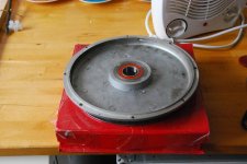
The threaded sidecover from John @ http://www.stealthelectricbikes.com.au has arrived today.

I will work this weekend on changing the sidecover thereby making my X5 disc compatible.

DSC_0134s.jpg

DSC_0135s.jpg
 
hi voicecoils: same thing I did on a x4 and I must add 2mm plate to get 17mm from disc to cover. I was using threaded cover with disc adapter. Then I fitted avid juicy 7 which is 14mm from inner side of disc. It will go without plate but i do not like to have less then 1mm space from cover to caliper.
 

Attachments

  • x4- PC100013.jpg
    x4- PC100013.jpg
    59.4 KB · Views: 2,710
HAL9000v2.0 said:
hi voicecoils: same thing I did on a x4 and I must add 2mm plate to get 17mm from disc to cover. I was using threaded cover with disc adapter. Then I fitted avid juicy 7 which is 14mm from inner side of disc. It will go without plate but i do not like to have less then 1mm space from cover to caliper.

Ahh good. I have a juicy 5 caliper.

I'll have to make a small spacer to keep the disc spaced out far enough. Perhaps I will use loctite on the threads as well.

Good to hear it can be done!!!
 
NEWS

Kurt's gotten back to me on the swingarm. Sounds like it's not too far off being ready to post back.

WOOHOO!

Then I can get it laced up to the rim I've got waiting.

Things are starting to come together, pretty happy about it :p
 
recumpence said:
Very cool!

I know what it is like on the front end of a large project. It feels good to get the project under way and nearing completion.

Matt

Thanks! My project should have been straightforward for the most part. However the frame, hubmotor, and controller all required modifications. That combined with the need to order many small parts from all over the world has slowed things down.

I'm very grateful to have:
* Received a FREE X5 :D
* the frame modified by forum member Kurt
* custom X5 screw on sidecover from forum member getadirtbike (http://www.stealthelectricbikes.com.au)
* Advice and guidance from many on E-S

I'm looking forward to the first ride and sharing the results and photos on E-S 8)
 
Hi Voicecoils,

hang in there bud, theres always a slight delay in accumalating all the right parts the all of a sudden the project comes together and is completed 8)
looking forward to seeing the giant in action :D

Cheers,

D
 
Cheers D! I'm meeting up with Andy from evmotorcycle.org Monday to check out an electric motorcycle rider in Sydney. Should be quite fun :p

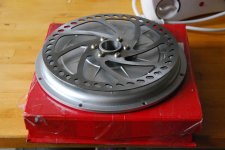
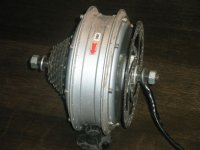
Got my X5 screw sidecover installed today so I can run a disk brake.

I used a small 100mm gear puller to pull against a Dura Ace fixed gear sprocket screwed on to the drive side of the X5. Screwed up nicely and made a great POP when the paint and glue broke. Ended up being pretty straighforward. I was expecting major dramas.

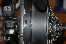
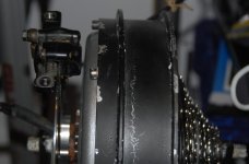
To top it off, the Dura Ace sprocket seems like the perfect spacer for clearance of my Juicy 5 caliper. Kurt tells me the swingarm could be ready Monday or Tuesday to be posted back. :p

Now, Pictures! (You have to be logged in for the first 3 pictures to show up. There are 5 photos in total.)

file.php

file.php

file.php


X5_caliper_spacing.jpg
X5_spaced_out.jpg
 
Did you not have that bolted down :shock:

I can hear the wife screaming at you now while you try to explain the scuff marks going all the way across the room.....
Would have made for great video!

So was that wobble caused by the axle sliding side to side in the stand or from hub being off axis?

-methods
 
Back
Top