Transerfer said:
How can I at least do a factory restore? Thanks!!
To do “factory reset” equivalent you need the original configuration file, unmodified. If you opened it, changed it and saved it under the same name, it might be corrupted.
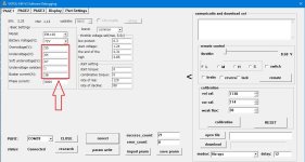
Hello BareKuda! I struggled with this problem for two days and nothing happened. I am sending 2 screenshots, on the first one the full original "ini" of the controller file. On the second, what is loaded after recording. What is circled in red does not change in any way. Whatever values I enter..
Do you have an idea what could be the problem? And what can I do to solve it? Thank you very much in advance!