Yamaha YZ250F

That's coming along great!

Maybe it is just the photo but the depth of the teeth on your front water jet sprocket looks much more than the JT sprocket, does the profile match? Longer tooth isn't bad for the small sprocket as long as it has clearance, it'll run nicely in the oil bath I believe.

PS how will you fill the oil, I don't see a fill or drain screw. And what cover will you use? Plexi would look cool! I believe it is oil resistant too and nice to see the chain and sprocket condition while you use it for the first few hours and monitor the condition.

How long do we think until QS start offering a reduction drive for this motor like the 3kw? [emoji1786]

cheers
Tyler

 
Since I didn't see a counter for : individual posts read. You might feel we are not interested.

Most of us couldn't build just a couple of the required parts not to mention all of them...

Just wanted to let you know that I for sure am having a blast reading about your workmanship!
 
Tyler, good eye :wink:
It is the edge of the profile that is different on the sprockets:

pq5bnkK.jpg


Where the teeth on other sprockets is cut off, these go all the way to the edge.

This is the side cover and fill hole:

5UKqlJ0.jpg


Yes, plexi would sure look cool. But I am afraid there would be problems with heat and getting it to seal properly.
I expect that the oil might get rather hot, so I think alu would be good for heat transfer too.

I will drill for a drain plug when I take it apart to finish welding the frame, there will be a hole for some sort of ventilation too.

Thanks for the comments :)
 
On the ground for the first time in a while:

RAH5BJt.jpg


Zip tied the wires etc. to be out of the way, and went for a little testride.
There sure are some tuning to do..
I had noticed sluggish throttle response and that it would keep accelerating a second after throttle release with the wheel in the air, and it was pretty much the same when driving :roll:
 
You mentioned 3D printing the controller cover. Not sure how much 3D printing you’ve done, but one idea to keep in mind; I don’t know how hot it will get in there, but make sure it won’t reach the glass transition temperature for whatever you print with. If the air around the controller gets high enough the box will start to sag. I’d recommend not using PLA.


Sent from my iPhone using Tapatalk
 
Philosoraptor said:
You mentioned 3D printing the controller cover. Not sure how much 3D printing you’ve done, but one idea to keep in mind; I don’t know how hot it will get in there, but make sure it won’t reach the glass transition temperature for whatever you print with. If the air around the controller gets high enough the box will start to sag. I’d recommend not using PLA.


Sent from my iPhone using Tapatalk

Well, I have done very little 3d printing.. Just some test prints that I haven't drawn myself. The idea was mostly that the controller cover would be an easy drawing to make to get started.
I dont think it will get very warm, but Im not sure. It will have a constant flow of air and dirt from the wheel. The plan was to do it in pla, but it is not a big problem if it dosent last.

For me it would probably be easier to make it in fiberglass :roll:

Frank, thank you.
 
Played around in the controller setting a bit more and got rid of the throttle response issue.
However it is still lacking power. I havent been able to test very much, it is dark outside when i get home.
But I have tested lower speeds a bit at least, and it wasn't very impressive.

u9dv0b1.jpg


I have been looking at these torque maps, and it is not looking good.
The problem seems to be the inductance, if I lower it there is a different story.
If I take out a zero so I get 13uH I get almost full torque all the way and a crazy output like 75kW or something.
Now it is like 15kW :(
Seems to match the battery amps I have been able to see on the phone so far too.

Am I missing something here or what? It cant be possible that I can only get 15kW from this motor?

A map on a zero motor:

INWC8KV.jpg


Both on these are in DCF files, I cant say if either of them are correct. It may be other settings that affect the result.
 
Those numbers don’t seem realistic in comparison. Roughy the same Ke but a 4x diff in inductance.. inductance is driven by coil turns, also Ke which is 1/Kv according to the info i've read.

Let's see.. I'll try to calculate around a bit
1 rpm, 1 rev/minute equals 2*pi/60 (rad/s) so translation factor between them is about 9.55 rpm per 1 (rad/s)

0.0296 V/(rad/s) is 0.0296 V/9.55rpm and Ke is 0.0031 V/rpm, Kv=1/Ke so Kv is about 323 and that seems too high. Is there a mismatch in the units of the numbers that was written somewhere?

Then is your motor an IPM? I guess so? Don’t know about the zero motor but at least an IPM could have as much fw current as 90deg current and still gain torque so i think this setting might be increased.

Where did you get the files?
 
My motor should be ipm. The zero motors might be, it depends of the year they are from.
I have 2 files with zero motors, their numbers match. One is supposed to come from nuxland and one from drbass.

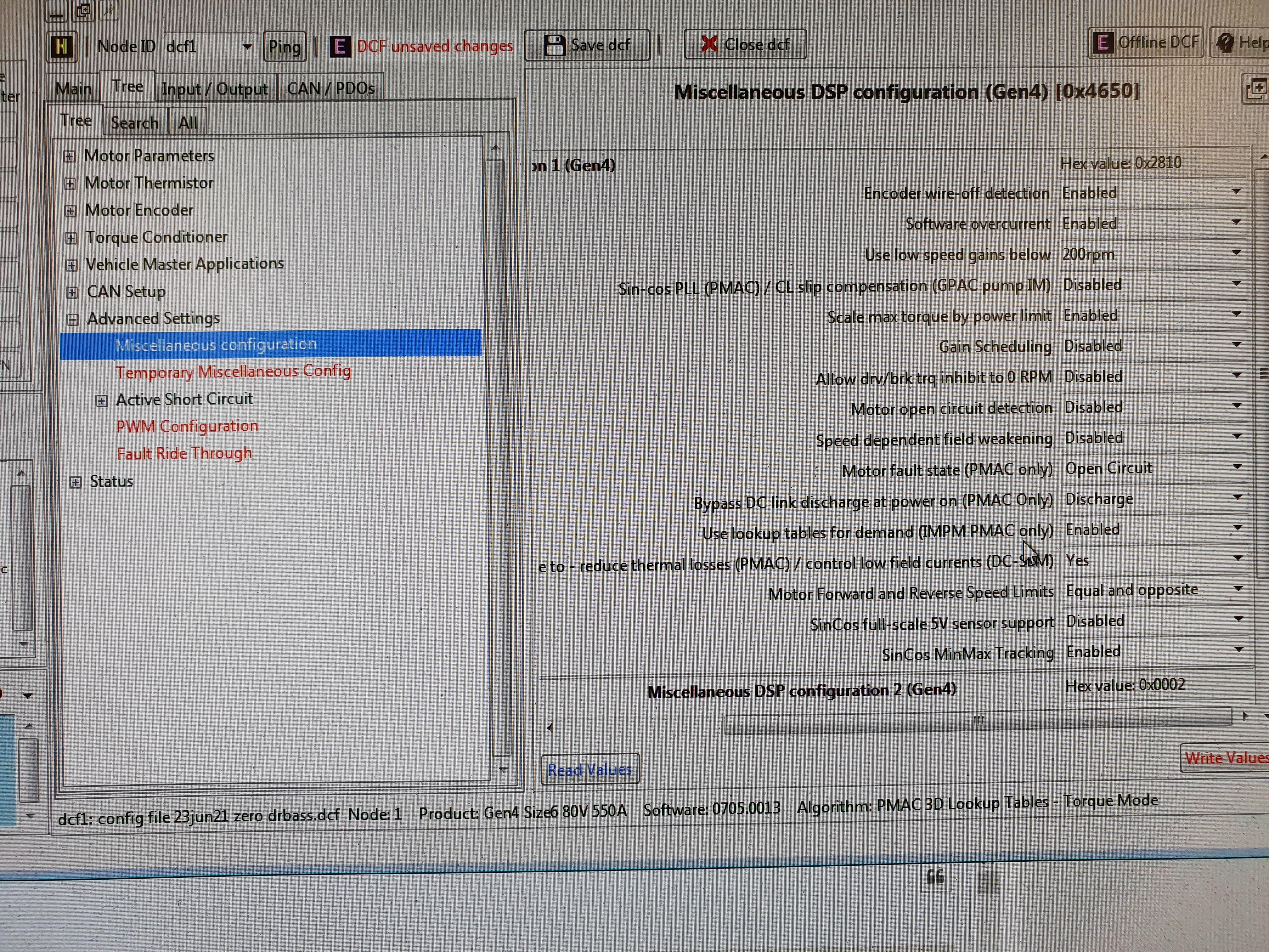
None of them or mine is set up like an ipm, and I dont know how to do it. I asked about it in the sevcon thread, but didnt get any replys.

It looks like this:

MI7BMu4.jpg


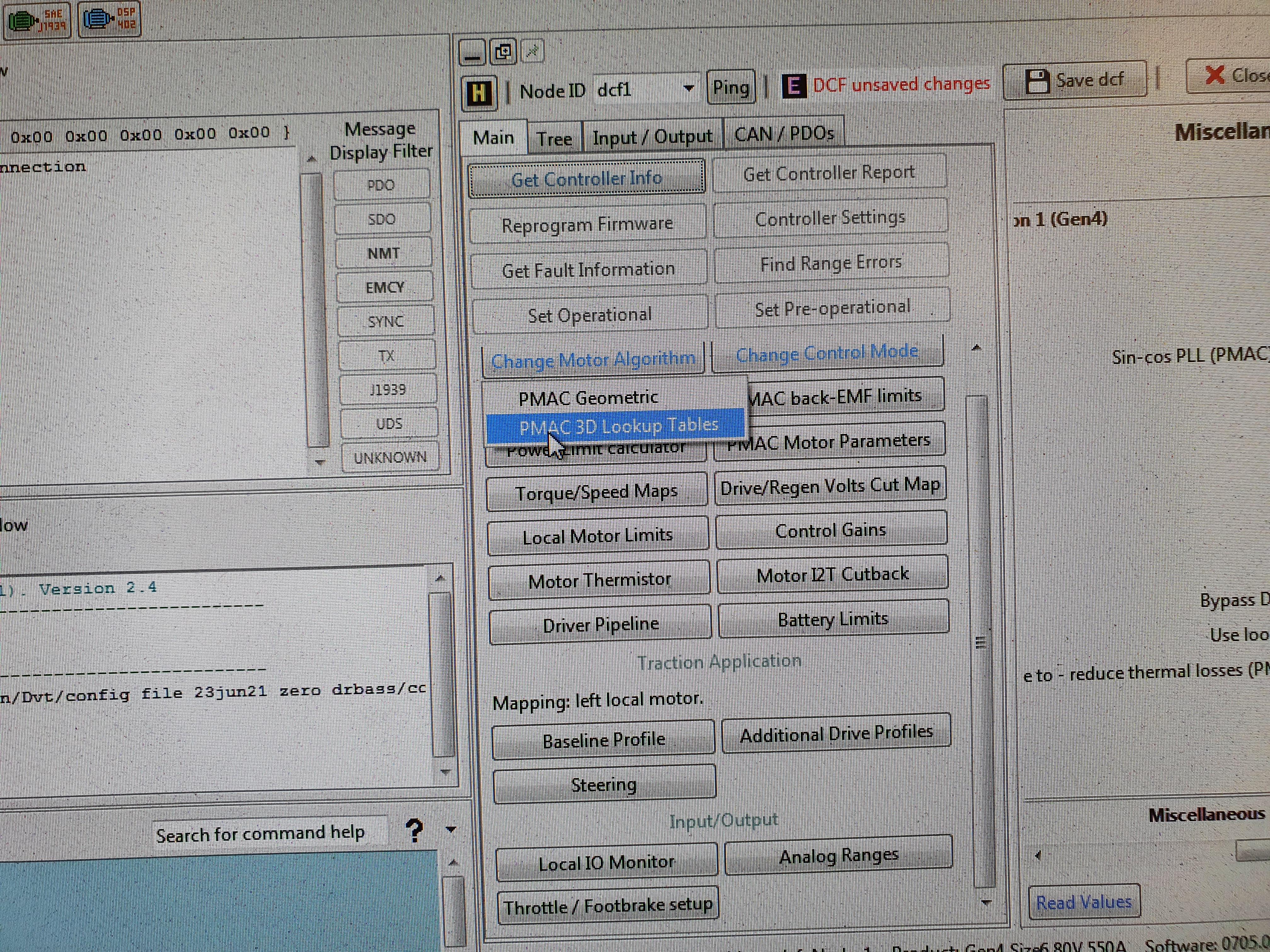
Here in the main setting I can choose "3D lookup tables" instead of "geometric" but the motor wont run if I do so.
Same thing here:

JYCPjMI.jpg


(where the arrow points) I can choose it, but the motor wont run.

Then there is this:

872Ex5f.jpg


That leads to this:

KUZEACD.jpg


I suppose this might be the settings, but it is password protected.
The warning is a bit worrying too :bolt:
 
interesting! What does the IPM lookup table contain then? empty table could explain why it doesn’t work

It seems the characterisation is a tool for creating a lookup table so it will step up d-axis and q-axis current gradually, you do it on a dyno to build an Iq and Id vs torque and rpm map. That's probably the reason for the warning, since it builds a map with a parameter sweep the motor/controller current can be set to be swept outside of the acceptable limits.

This is catching my interest, feel like getting a Sevcon and start fiddling with it.
 
I dont know what the lookup table contains, I havent been able to find any..
It can be that it is written on an external file, that you then upload somehow. It is like that when setting encoder offset and ke.

It is expensive to start fiddling, you need to buy both controller, ixxat adapter and program.
It is better that you come and fiddle with this one..
Or finish your dyno, and I can come to you :wink:
 
Ok, so I just went and put 50 in in the inductance field and checked the real time data.
It showed measured inductance 65uH instead of the 130 it showed before..
Changed to 30, still got 65. Changed to 65 and did a new torque map:

pIFctQv.jpg


So it looks like double the power, it will be interesting to testdrive.
 
Good luck :wink:
where are the previous numbers from? Autodetect function? They don’t seem to make sense. Two Ke that aren’t the same, a Kt that does not match the Ke, either the settings are mixed up or it’ll be tough without a proper manual..

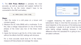
I’d do a drill press Kv measurement (i guess it isn't new info but anyway) to rule out that the nucular introduces some measurement error. Just put AC rms volt and rpm into the formula here:
https://www.bavaria-direct.co.za/constants/
543341CB-7386-40DC-BB0F-9F3272193346.png

Since you have it on your bike you could use a cordless drill to spin motor, film the voltage measurement and the rpm measurement with your phone to get good values even if it's floating a bit.
 
j bjork said:
I continued with some more measurements on the motor.

I did some tests of resistance by connecting a load in series with the motor and measure voltage drop.
I tested with two different loads, a little under 8A and a little over 40A.
I got the same results of very close to 5mohm, so I think that is about correct.
I will probably try with a better A meter just in case, but I dont think it will change much.

I then measured back emf, from what I read it is the right way to determine Kv.
I tried some different methods, with a multimeter and with oscilloscope.

From what I read I should take the multimeter value x 1,414 (to convert from rms to peak) then x 0.95.
Then the rpm / with that value.
With the oscilloscope I get this:

FgaQEmh.jpg


This should be at 1332rpm.

The Kv seems to be about 61, I guess if measured with a controller it would be a little less.

I did something similar with oscilloscope earlier, I found the post now.

I type in the configured Ke, pole pairs, inductance etc.
I get the Ke autodetected when I set up angle offset.

I suppose when I measured inductance I got 2 winds presuming the motor is connected in Wye.
The controller found it ok, as it couldnt see Wye or D connection.
When I lowered the value, the controller presumed Wye, and switched from 130 to 65uH measured value.

This is just guesses from me, as I dont really know how it works. But it sounds likely to me :wink:

I have also measured inductance on the 138 70h and got around 70uH, that could probably be halved too in that case..

Anyway, did a testdrive earlier, it was a lot of difference. It kicks pretty good at speed now, and from my logs from the bms I seem to be pulling about the 31kW that my torque map shows.
But at low rpm it is a bit sluggish. I dont think I get the 135Nm
 
j bjork said:
I dont know what the lookup table contains, I havent been able to find any..
It can be that it is written on an external file, that you then upload somehow. It is like that when setting encoder offset and ke.

It is expensive to start fiddling, you need to buy both controller, ixxat adapter and program.
It is better that you come and fiddle with this one..
Or finish your dyno, and I can come to you :wink:
Heaven help us if you guys start collaborating with a Dyno, that motor will blow your socks off!

Hoping you get the controller figured out jbjork! Sevcon is complicated but rewarding when it's set up right.

cheers
Tyler

 
I know that you don't like posting in Electric Motorcycle Builds Facebook group but i can tag a handful of Sevcon experts which might be able to help you figure out the settings . One of them is an owner Voltsport UK . The only one i know here is Arlin Samsone as Arlo1
j bjork said:
Played around in the controller setting a bit more and got rid of the throttle response issue.
However it is still lacking power. I havent been able to test very much, it is dark outside when i get home.
But I have tested lower speeds a bit at least, and it wasn't very impressive.

u9dv0b1.jpg


I have been looking at these torque maps, and it is not looking good.
The problem seems to be the inductance, if I lower it there is a different story.
If I take out a zero so I get 13uH I get almost full torque all the way and a crazy output like 75kW or something.
Now it is like 15kW :(
Seems to match the battery amps I have been able to see on the phone so far too.

Am I missing something here or what? It cant be possible that I can only get 15kW from this motor?

A map on a zero motor:

INWC8KV.jpg


Both on these are in DCF files, I cant say if either of them are correct. It may be other settings that affect the result.
 
ray88, I will consider posting there :wink:

larsb, I tried and it dosent seem right:

qzxhB7V.jpg


a8NnHuJ.jpg


I tested it on the stand, sluggish response and just kept going when I released the throttle.

I also tried 0.0165, it didnt seem right either:

6WSaoU7.jpg


APNMOn2.jpg


I also tested one of these angle setups again, sevcon thinks it should be 0.0964. I think I have seen 0.094, 0.095 or 0.096 every time.
It cant have something to do with that it measures in rms?

6hbf9pc.jpg
 
Back
Top