• Howdy! we're looking for donations to finish custom knowledgebase software for this forum. Please see our Funding drive thread

"Zephyr" - Finally, the "v4" Fechter/Goodrum/Hecker BMS...

Is the only difference between 4.4 and 4.4.1 the R2 connection change?
It would be helpful to have a running update log to show what is new for each version. :wink:
Thanks - Nate
 
Nate said:
Is the only difference between 4.4 and 4.4.1 the R2 connection change?
It would be helpful to have a running update log to show what is new for each version. :wink:
Thanks - Nate

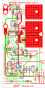
Actually, for v4.4.1, Richard came up with a slightly better way to handle the parts tolerance issue with the LED shutoff. Instead of moving the top of R2 to the unswitched +12V line, instead we leave R2 alone, and move the Vcc input for U2 from the unswitched +12V to the switched +12V. Here is what the "hack" would look like to do this mod to a v4.4 board:

24-Channel BMS-NL-v4.4.0c Charge Controller.png

Orders from this week will use the v4.4.2 version. For the few I received after we made the v4.4.1 change, I went ahead and modified the boards, including installing the TPS2812 U2 chip, as there wasn't a convenient way to add the wire to pin 6 without the chip installed.

I agree, a log file would be good, but I don't have time, at the moment.

-- Gary
 
Thanks Gary, that helps. Luckily I have not soldered up the charge control circuit yet so I will make the change to U2 instead.
I understand about the time constraints. Thanks again to you Andy and Richard for making this happen and continuing to support it.
 
SlyCayer said:
I need replacements for these:

595-TPS2812P

647-UMA1C470MDD1TE

Everything else seems in stock...


For the capacitors, you can substitute any of these:
140-SS470M1E0605P

140-SS470M1C0605P

140-L25V47-RC

140-L16V47-RC

Mouser shows 221 in stock on 595-TPS2812P right now.
alternate is 595-TPS2812PE4 (223 in stock)

Newark also has them in stock:
Newark part# 77C0202
http://www.newark.com/
 
SlyCayer said:
Thank you Richard... I ordered the parts and the board.

If I may ask, why 2 cases for the 24 channels?

Because they don't make one box that is long enough. The longest of these Hammond extruded aluminum boxes is 8.66" The 16-channel version, plus the charge control section, just fit in this size. For the 24-channel variant, Two 6.3" long versions can be stuck together, side-by-side, Which makes a 12.6" wide box. The full 24" board is a bit over 12".

-- Gary
 
Hi,
i'm will order the BMS the next days, but i'm still not sure about the right setup. I'm building a 6p24s Pack out or Turnigy 20C 6s Lipos. I have concerns about the 1 LVC circuit for 6 parallel cells. So i was thinking about 2 parallel lvc circuits (for 3 parallel cells). Is this necessary? When one cell in a 6p pack goes down i will recognize it by far later on the lvc than with a 3p pack. If this statement is wrong please educate me.
Now with the great Zephyr and the ease of bulk charging i thinking about using the Zephyr. The question is the setup. Is it possible to use 2 Zephyr in parallel? Does it make more sense to make a combination of 1 Zephyr and 4 TPPacks LVC Boards? Or is 1 Zephyr enough?
Thanks for your help.

Martin
 
mj2412 said:
Hi,
i'm will order the BMS the next days, but i'm still not sure about the right setup. I'm building a 6p24s Pack out or Turnigy 20C 6s Lipos. I have concerns about the 1 LVC circuit for 6 parallel cells. So i was thinking about 2 parallel lvc circuits (for 3 parallel cells). Is this necessary? When one cell in a 6p pack goes down i will recognize it by far later on the lvc than with a 3p pack. If this statement is wrong please educate me.
Now with the great Zephyr and the ease of bulk charging i thinking about using the Zephyr. The question is the setup. Is it possible to use 2 Zephyr in parallel? Does it make more sense to make a combination of 1 Zephyr and 4 TPPacks LVC Boards? Or is 1 Zephyr enough?
Thanks for your help.

Martin

While it is true that in a 6p configuration, the other five cells will "help" a weak cell, they are all still going to be protected. When cells are connected in parallel, their voltages will automatically equalize, so from that point forward can be treated as one larger cell. A dying cell will pull the others down, and yes it might take a little longer with 6 instead of 3, but in the end as long as the LVC function is there, it will keep the cells from going to far.

A weak cell will also manifest itself when charging because a dying cell will have a reduced capacity, which means the block of six cells will also have a reduced capacity. During charging, this block will get full faster than the others so you will see its LED come on before the rest. You can tell a lot about the general health of the pack by just watching how and when the LEDs come on. Whatever the pattern, it will usually tend to be close to the same, from charge to charge. That pattern will change if you start to get a wonky cell/block.

Anyway, I think one BMS is fine, even for a 30Ah pack.

-- Gary
 
SlyCayer said:
I will be having a 46Ah battery pack, charge A of 20A, do I need to add anything extra for that charge current?

Please let me know asap.

Best bet is to populate both main FET positions, but even with one it should handle 20A without getting very warm. Also, at that current, the sensing resistor (the 5 milliohm one), will get pretty hot, but it's solid metal and can take it. Just be careful not to let wires touch against it when you build the board.
 
fechter said:
Best bet is to populate both main FET positions, but even with one it should handle 20A without getting very warm. Also, at that current, the sensing resistor (the 5 milliohm one), will get pretty hot, but it's solid metal and can take it. Just be careful not to let wires touch against it when you build the board.

So you are saying I should put 2 X Q3 in the 2 positions on the board that says "Q3"? I only ordered 1 from Mouser, I will have to order just a Q3 alone from them.

Can we do something to maybe lower the heat of the 5 milliohm sensing resistor?

Also, I noticed on the board, the Throttle: +5V, Sig, Grd and Controller: +5V, Sig, Grd

Is this a half throttle option mounted directly on the board and integrated? Do I simply have to connect my throttle to the 5V, Sig and Grd of the Throttle side and same with the controller side going to the controller and when the LVC will activate it will half throttle automatically?

You guys thought about everything, thank you Richard, Gary and Andy, you are just amazing.
 
I think you'll be fine with just one Q3. On your first charging cycle, check the temperature of it a few times. If it gets really hot (which it shouldn't), you can always add a second Q3 later.

Yes, the board has the throttle pull down parts integrated. You just have to loop the throttle cable through the BMS and make the connections to the board. Alternately, if looping the throttle cable is impractical, you can bring a pair of wires out from the LVC and ground connections, and tie into the throttle cable remotely. This would require installing a resistor at the tie-in point.

At 20A, the sensing resistor will be dissipating 2W. It's rated for 5W. It might get up to 100C, which is fine. I don't have a enough power supply to test one at a full 20A, so I don't really know exactly how hot it will get. The only way to reduce the heating would be to use a second one in parallel or to change the value lower, which will affect the calibration of the cutoff current. I would suggest using the stock value and seeing how hot it gets. If it's getting too hot, either a lower value or a second one in parallel will bring it way down. Most setups will only take full current for a while when you first start charging a fully depleted pack. The current will start to taper off as the cells come up and you'll probably spend most of your time at less than the limit.
 
fechter said:
Most setups will only take full current for a while when you first start charging a fully depleted pack. The current will start to taper off as the cells come up and you'll probably spend most of your time at less than the limit.

True, I will only be charging at 20A for about 1 hour.

Thank you again for your great help.
 
SlyCayer said:
fechter said:
Best bet is to populate both main FET positions, but even with one it should handle 20A without getting very warm. Also, at that current, the sensing resistor (the 5 milliohm one), will get pretty hot, but it's solid metal and can take it. Just be careful not to let wires touch against it when you build the board.

So you are saying I should put 2 X Q3 in the 2 positions on the board that says "Q3"? I only ordered 1 from Mouser, I will have to order just a Q3 alone from them.

Can we do something to maybe lower the heat of the 5 milliohm sensing resistor?

Also, I noticed on the board, the Throttle: +5V, Sig, Grd and Controller: +5V, Sig, Grd

Is this a half throttle option mounted directly on the board and integrated? Do I simply have to connect my throttle to the 5V, Sig and Grd of the Throttle side and same with the controller side going to the controller and when the LVC will activate it will half throttle automatically?

You guys thought about everything, thank you Richard, Gary and Andy, you are just amazing.
You can try one FET initially - especially if you ordered the FDP036N10A. I've used a single 4110s for 77V (21S LiFePO4) at 13A and it hit about 140°F. Two 4110s get up to about 135-140°F at 77V 16A. Warm enough to notice but not a problem either way.

The current sense resistor will get hot at those levels - enough to sizzle sweat off a finger tip and quickly convince you to pull pack. ;) But just keep wiring away and it'll be fine.

Exactly right on the throttle. You really only need three wires - a ground and the two signal wires - between the throttle and controller.
 
AndyH said:
[I've used a single 4110s for 77V (21S LiFePO4) at 13A and it hit about 140°F. Two 4110s get up to about 135-140°F at 77V 16A. Warm enough to notice but not a problem either way.

My set up is 24S20P(88.8V and 46Ah), and I will be charging at 20A? Do you think this could be a problem? If your get up to 140F at 77V 16A, mine will go up to 400F and I will be able to cook beef on the FET.

Let me know if I am wrong.
 
SlyCayer said:
AndyH said:
[I've used a single 4110s for 77V (21S LiFePO4) at 13A and it hit about 140°F. Two 4110s get up to about 135-140°F at 77V 16A. Warm enough to notice but not a problem either way.

My set up is 24S20P(88.8V and 46Ah), and I will be charging at 20A? Do you think this could be a problem? If your get up to 140F at 77V 16A, mine will go up to 400F and I will be able to cook beef on the FET.

Let me know if I am wrong.

I too think it will be fine, even with one FET. If it gets too warm, you can add a finned heatsink to it, or just use two FETs.

-- Gary
 
fechter said:
Yes, the board has the throttle pull down parts integrated. You just have to loop the throttle cable through the BMS and make the connections to the board. Alternately, if looping the throttle cable is impractical, you can bring a pair of wires out from the LVC and ground connections, and tie into the throttle cable remotely. This would require installing a resistor at the tie-in point.
Hi
Just. Quick note on if you decide to take the route of taping the LVC and ground like on the LVC / LVC HVC boards I have had a small circuit board made up for the LVC boards I had made, they will work with gary's LVC boards and the LVC output from the zephyr, it basically is wired the way Gary said to wire in the LVC boards in his diagram, it already has the SMD 1K resistor fitted, it also has the components fitted needed for the brake line on the CA. It can be fitted extremely inline with the throttle cable or if you have a infineon controller any model it can be fitted inside the controller, I am having plenty made and I can send a load over to fecter to be added to the zephyr extras if wanted, this board takes the wory out of did I put the resistor in the right place.
The board will be ready in a few weeks.

Geoff
 
geoff57 said:
Quick note on if you decide to take the route of taping the LVC and ground like on the LVC / LVC HVC boards I have had a small circuit board made up for the LVC boards I had made, they will work with gary's LVC boards and the LVC output from the zephyr, it basically is wired the way Gary said to wire in the LVC boards in his diagram, it already has the SMD 1K resistor fitted, it also has the components fitted needed for the brake line on the CA. It can be fitted extremely inline with the throttle cable or if you have a infineon controller any model it can be fitted inside the controller, I am having plenty made and I can send a load over to fecter to be added to the zephyr extras if wanted, this board takes the wory out of did I put the resistor in the right place.
The board will be ready in a few weeks.

Geoff

That will be a good option for those that don't want to bring the throttle cable through the BMS. It can be tied into the LVC on the Zephyr with a pair of wires.
 
fechter said:
That will be a good option for those that don't want to bring the throttle cable through the BMS. It can be tied into the LVC on the Zephyr with a pair of wires.
Sorry, mind elaborating on that? At present my throttle goes straight to the controller which is mounted inside the motor. The battery is merely connected to the motor by two wires. Why would I want to bring the throttle to the BMS? I noticed the connections on the PCB drawing but didn't pay much attention. The controller appears to have a voltage measuring capability as the throttle unit LED glowed orange yesterday, instead of green. I checked my cell log which I have in parallel and found one bank of cells had dropped to 2V (8s pack No5) so I stopped using it and pedalled home :( :(
Put it on charge, but that is why I need the BMS to re-balance them (Only second use cellman)
 
Gregb said:
Sorry, mind elaborating on that? At present my throttle goes straight to the controller which is mounted inside the motor. The battery is merely connected to the motor by two wires. Why would I want to bring the throttle to the BMS? I noticed the connections on the PCB drawing but didn't pay much attention. The controller appears to have a voltage measuring capability as the throttle unit LED glowed orange yesterday, instead of green. I checked my cell log which I have in parallel and found one bank of cells had dropped to 2V (8s pack No5) so I stopped using it and pedalled home :( :(
Put it on charge, but that is why I need the BMS to re-balance them (Only second use cellman)

The idea is when the cells get too low, it will kill the throttle, which will stop the discharge and at the same time give you a hard to miss indication that your cells are nearing completely empty. In practice, you normally hit LVC when the discharge current it high (full throttle). This gives a sudden loss of power that's hard to ignore, but the cell voltages will immediately recover and restore the throtte. The throttle drops out for a fraction of a second. If you keep on the throttle, it will keep 'hitting', and throttle will stay off for longer and longer periods. If you back off the throttle when it first hits, you can keep going for a while.

Alternatively, you can use the LVC signal to activate an alarm, but that might take an additional relay or something. We're also working on an 'Active Cutoff' which completely kills the power to the controller on LVC. This requires the cutoff circuit can handle the full controller current, so it takes quite a bit of silicon. This could also be kind of rough on the controller.
 
All this talk of the LVC has got me a little confused. Will the LVC connection work the same as the 2.3.x version? Can I just hook it up to the brake input on my Crystalyte controller?
Thanks - Nate
 
Nate said:
All this talk of the LVC has got me a little confused. Will the LVC connection work the same as the 2.3.x version? Can I just hook it up to the brake input on my Crystalyte controller?
Thanks - Nate

Yes, it is exactly the same. Many setups, however, now use regen braking, so you don't want the LVC engaging regen. :eek: :roll: So now what we recommend is that you tie the LVC directly into the throttle signal, instead of the brake input.

-- Gary
 
Back
Top