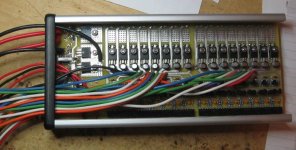
"Zephyr" - Finally, the "v4" Fechter/Goodrum/Hecker BMS...

why does the web page refer to 12/16 ? (in configurations of 12/16, 24 and 32-channels.) This may be misleading to those who have 8s setups....
 
Gregb said:
why does the web page refer to 12/16 ? (in configurations of 12/16, 24 and 32-channels.) This may be misleading to those who have 8s setups....

That is misleading, leftover from a previous variant. I will fix that.

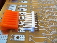
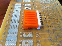
As for the connector problem, we are looking into that. There are several options. There is a 90-degree version of the MTA 156 connector that will work, if the BD156 transistors and the 47uF caps are also mounted from the bottom.

Zephyr BMS-05.jpg
Zephyr BMS-06.jpg

Another option would be to use the taller version of the Hammond box, but that will require a different custom end plate. There's also a lower profile set of connectors/headers that will fit in the same hole pattern as the MTA 156 series, but these require that you crimp pins on the wires. Finally, the wires can be soldered directly to the board and an external set of connectors used.

Zephyr BMS-07.jpg

As soon as we get this sorted out, I will finish off the instructions, and put the link on the first post.

-- Gary
 
What about cutting a notch for the connector in the top of the case?
 
What gauge wire is used for the different parts of the board?

I received my board in the mail a few days ago, thanks for the crazy fast shipping Gary. I just got all my mouser parts today. That is too bad about the balancing connectors, but now that I see the board in the box I think I will try to build mine with all the wires under the board and maybe make a custom end plate. I'm guessing I will have to move the board up a notch and use the aluminum block. I also want to put a clear top on it so I can see the board and LEDs. :wink:
- Nate
 
Actually, the 90-degree part looks like it will work fine, and the there is just enough room for the 47uF caps to mount from the bottom, along with the BD136 shunt transistors.

Zephyr BMS-09.jpg

I'm glad this will work, because it cuts a ton of time off the assembly process, not having to strip a crapload of wires, and then crimp pins onto them. :roll: :)

-- Gary
 
Gary -
No go for me, I had to buy the taller caps since the others were out.

How will the LEDs work on this board compared to the v2.x? Will they be on for a shorter time?
Thanks - Nate
 
Nate said:
Gary -
No go for me, I had to buy the taller caps since the others were out.

That shouldn't be a problem, as they can simply be laid over. I normally do this with tall caps anyway.

Nate said:
How will the LEDs work on this board compared to the v2.x? Will they be on for a shorter time?
Thanks - Nate

They will operate pretty much the same, coming on when the shunts are on, but now, when the cells get closer to balancing, the LEDs will dim, and then go out, once the cells are all balanced. When you watch the charge process, you can see the LEDs for the high cells come on, get bright, dim, and then go off, just before the main LED turns green, and the charge current shuts off.

-- Gary
 
Nate said:
Gary -
No go for me, I had to buy the taller caps since the others were out.

How will the LEDs work on this board compared to the v2.x? Will they be on for a shorter time?
Thanks - Nate

Dang! those things sold out already?
Alternate stubby capacitors (Mouser part numbers):

140-SS470M1E0605P

140-SS470M1C0605P

140-L25V47-RC

140-L16V47-RC

On the LEDs, it will depend on where the charger voltage is set. If you crank the CV setting higher, all the LEDs will light up at end of charge, but there will be a bit more heating. If you get the voltage just right, they will all light up dimly when everything is balanced but not generate much heat.
 
Thanks Guys,
I got these: 647-USV1C470MFD
I think they should work OK but they are 7mm high and more expensive. No big deal since I will be soldering the balancing wires direct to the board.

Gary - How are the instructions coming along?
- Nate
 
fechter said:
On the LEDs, it will depend on where the charger voltage is set. If you crank the CV setting higher, all the LEDs will light up at end of charge, but there will be a bit more heating. If you get the voltage just right, they will all light up dimly when everything is balanced but not generate much heat.

Actually, you don't want to set the charger/supply voltage higher than the point just before the shunts, and the LEDs start to come on. If the shunts are on at the end, there will be current flowing through so the low current end-of-charge detection logic won't trip. With a balanced pack, the sum of the cell voltages will be just below the point the shunts/LEDs turn on.

-- Gary
 
Nate said:
Gary - How are the instructions coming along?
- Nate

The connector issue threw me a bit of a curve, earlier today, or I would've finished them today. I'll get them done before the end of the weekend, for sure. :)

--Gary
 
GGoodrum said:
fechter said:
On the LEDs, it will depend on where the charger voltage is set. If you crank the CV setting higher, all the LEDs will light up at end of charge, but there will be a bit more heating. If you get the voltage just right, they will all light up dimly when everything is balanced but not generate much heat.

Actually, you don't want to set the charger/supply voltage higher than the point just before the shunts, and the LEDs start to come on. If the shunts are on at the end, there will be current flowing through so the low current end-of-charge detection logic won't trip. With a balanced pack, the sum of the cell voltages will be just below the point the shunts/LEDs turn on.

-- Gary

Actually, this may be a preference thing. The end-of-charge detection setting can be set higher than what the shunts take, so can still turn off even if the shunts are running if it's set high enough. If the charger voltage is low enough so the shunts are all off at end of charge, the detector would be set to a lower current. It can work either way. The advantage of running the shunts 'hotter' at end of charge will be faster balancing. This may be desirable for really out-of-whack packs. It will also increase the heating at end of charge, so adequate cooling will be required.

If the charger voltage is at the point where the cell LEDs are barely lit, there is essentially no shunt current, but the voltage setting will be very sensitive.

The safest setup would be to set the CV voltage a little low so even if there is some drift in the circuit, it won't turn the shunts full on at end of charge.

Setting the EOC current detector a little high will terminate the charge earlier, which may help cycle life at the expense of not getting 100% full charge. Charging to 95%, for example, may improve cell lifespan.

We may need to experiment a little to figure out the optimum settings.
 
GGoodrum said:
The connector issue threw me a bit of a curve, earlier today, or I would've finished them today. I'll get them done before the end of the weekend, for sure. :)
Sorry to bug you, but are the parts lists going to be revised in the light of the connector issue? I'm about to get the board, but want to hold off getting parts until the list has been 'debugged' a little. It's lots more expensive ordering internationally from mouser, and I want to get it right first time if possible...
 
Everyone hold on ordering parts. My V4.4 controller isn't quite right - something happened from the pre-production V4.3.5 to the final V4.4 board. We're backtracking now to figure out why the auto shut-off isn't behaving itself.
 
An update...

I have built up a "stock" v4.4 charge control section, and it works perfectly. We're still trying to figure out why Andy's is having problem with the auto turn-on/shutoff, but on mine, it works just fine. His works for everything but the actual turning off the LED logic. Without the charger connected, and on, the LED should stay off. When the charger is connected, the LED comes on orange. When the current drops below the adjustable low current level, set by the pot, the charge current is cut and the LED turns green. This part works fine on Andy's as well. The LED will stay on and green as long as the charger is still connected. When you disconnect the charger, the LED is supposed to go off. On mine, this happens, but on Andy's, it stays on.

We will get this sorted out today, and then I will get back to finishing the instructions. :)

I have modified the BOM file so that it shows the 90-degree MTA 156 connector as primary, and the straight one as an alternate.

-- Gary
 
Gary's build confirms the V4.4 circuit board - nice job!

I still haven't solved my controller problem but have built up some good troubleshooting data. It's looking like my "first article curse" strikes again. :evil:

I'm thinking we can turn-off the seatbelt sign and feel free to move about the cabin. :D
 
Hi
So is the zephyr board good to buy or should we hold off till the problem has been identified.

For anyone that is interested I will shortly have parallel balance boards ideal to use with the zephyr they have 1 mm tracks top and bottom, it can be configured 2 ways, the first is with the standard 22 gauge JST HX connector with silicone covered wires with capabilities for 20Ah, the second is with 18 gauge wire output that can be fitted into a row of pads at one end of the board this is ideal for mateing up with the zephyr balance connectors it also gives you an extra JST HX input connector making 5 so capable of up to 25Ah. The boards come with lacquer covering to keep the tracks insulated also a pics of foam is provided for the underside this stops shorts where the solder points are.

Geoff
 
geoff57 said:
Hi
So is the zephyr board good to buy or should we hold off till the problem has been identified.

For anyone that is interested I will shortly have parallel balance boards ideal to use with the zephyr they have 1 mm tracks top and bottom, it can be configured 2 ways, the first is with the standard 22 gauge JST HX connector with silicone covered wires with capabilities for 20Ah, the second is with 18 gauge wire output that can be fitted into a row of pads at one end of the board this is ideal for mateing up with the zephyr balance connectors it also gives you an extra JST HX input connector making 5 so capable of up to 25Ah. The boards come with lacquer covering to keep the tracks insulated also a pics of foam is provided for the underside this stops shorts where the solder points are.

Geoff

Those balance boards sound perfect. :) That will be great for LiPo-based setups.

We are moving full speed ahead. Try as I might, I could not get my board to fail at all. It works exactly the way Richard told me it would work. We still aren't sure what gremlins got into Andy's, but Richard will take a look at it later. Andy has a new one on the way, along with my good one, so he can see if it might be something unique to his setup.

I have finished the instructions, and have posted them in the first post of this thread. The orders I received to date have all shipped, as of today, and have the printed instructions included.

-- Gary
 
What happens if we buy everything and end up with Andy's problem??
Andy I expect you don't need help trouble shooting but have you for example replaced all the capacitors. In my experience, 30+ years, an out of spec capacitor can cause all sorts of problems. Once chased a problem for over a week because had been assured these new fangled tantalums never broke down........ :roll: :roll: :shock:
won't go into my Valve stories. and the Miller effect. :mrgreen: :mrgreen:
 
Gregb said:
What happens if we buy everything and end up with Andy's problem??
Andy I expect you don't need help trouble shooting but have you for example replaced all the capacitors. In my experience, 30+ years, an out of spec capacitor can cause all sorts of problems. Once chased a problem for over a week because had been assured these new fangled tantalums never broke down........ :roll: :roll: :shock:
won't go into my Valve stories. and the Miller effect. :mrgreen: :mrgreen:

Not likely you'll have these issues, but whatever the problem, we'll make it right. Part of what makes this difficult is that Richard is off on vacation this week, so he hasn't been able to participate much. He'll be back Saturday, though, and he'll have a little present waiting for him. ;)

-- Gary
 
Members of ES may want to give more credit to Goodrum and Fechter for all the free work they have put into this project. If you buy a product from Costco or Best Buy you can expect warranty coverage and a good return policy. Low product custom made products like ebike bms circuits are in the Ferrari category exclusive, expensive and a bit temperamental.
 
I'm sorry but why would you assume that? I think what they have done is tremendous and assume every body else that hangs around here does too..... :)
 
Hi
I just want to check on somthing if we want to use meanwell PSU's or meanwell copies / clones do we still need the meanwell CC/CV board that first fechter did then Gary did one with more features.

Geoff
 
Back
Top