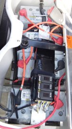
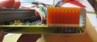
"Zephyr" - Finally, the "v4" Fechter/Goodrum/Hecker BMS...

auraslip said:
There is also now an "Alarm" output that can drive a buzzer, or a 12V relay, for instance, instead of cutting the throttle signal. This sort of LVC method, either the trhottle or the alarm signal, means there's no limit on discharge current for this BMS design. The discharge wires do not need to connect to the BMS at all.

Does this mean there is a 12v output to power the coil of the relay?

Yes, that is right. I don't remember the max current draw, but Richard can pop in and provide that. :)
 
chxs said:
And using 652-3362X-1-102LF insted of 652-3362F-1-102LF is ok ????
I ordered the alternate 652-3319P-1-102 as well as the 652-3362H-1-102LF and 652-3362P-1-102LF just in case.

The 652-3362X-1-102LF is a side mount. U3 might get in the way of a side adjustment... Here is a link to the Data sheet: http://www.bourns.com/data/global/pdfs/3362.pdf
- Nate
 
I assume for an 8s setup one needs to order all the parts listed less than 16 (eg 1,2, 4 etc) and just change the 16 to 8 for all the others???
 
I'm confused about the board. I count 24 little circuits on the board (three groups of eight), yet we're supposed to have two separate boxes for a 24s setup, and presumably two boards...?

What's going on here? :?

Also, there are two separate power connections, one at each end. Are these for two separate chargers, if so how many cells do they each serve and what should the voltage be?
 
Zenid said:
I'm confused about the board. I count 24 little circuits on the board (three groups of eight), yet we're supposed to have two separate boxes for a 24s setup, and presumably two boards...?
I was confused about this at first too. If you reread the fist post it explains the 2 boxes in the 24 BOM are to be combined to make a single box long enough to accept the longer board. I will be building the 16 with the extra 8 channels as a future upgrade, so I used the 16 BOM box and all the rest of the parts from the 24 BOM.
Zenid said:
Also, there are two separate power connections, one at each end. Are these for two separate chargers, if so how many cells do they each serve and what should the voltage be?
I think you are referring to the two types of end plates for the box that are removable from the printed circuit board. If so, you would only use the one pertaining to your build so 16 or 24 channels and the other side of the BMS box would be blank.
- Nate
 
GGoodrum said:
auraslip said:
There is also now an "Alarm" output that can drive a buzzer, or a 12V relay, for instance, instead of cutting the throttle signal. This sort of LVC method, either the trhottle or the alarm signal, means there's no limit on discharge current for this BMS design. The discharge wires do not need to connect to the BMS at all.

Does this mean there is a 12v output to power the coil of the relay?

Yes, that is right. I don't remember the max current draw, but Richard can pop in and provide that. :)

The alarm line was added kind of last minute. As is, it can drive a maximum of about 30mA. This could possibly drive a small 12v relay, or for sure a solid state relay. I was thinking more like a piezo alarm that draws less than 30mA hooked up directly. I'll try to refine this a bit more to see if there's a good relay that can drive directly. A G3VM solid state relay (with a drive resistor) can handle 120mA load.
A Tyco TSC-L series mechanical relay should work well and is rated for 1A.
 
Here's a very quick and very crude overview of what to expect with the V4.4 BMS. The functions are very 'modular' compared with the V2.x boards - the control section can be used independently of the channels, and each 8S block of channels is independent. While I'm using a V4.1.5 channels in the demo, one can use the new BMS in one box or can cut the sections apart and put them into multiple smaller boxes if that's better for the design.

And since the control section only needs the two HVC wires during charging, the control section can be left off the bike if one wishes - the LVC signal remains 'with the channels' for pulling the throttle down. (Though one would need to add a current limiting resistor for the throttle connection if they decide to leave the controller at home.)

[youtube]djw-VRqyXkg[/youtube]
 
The alarm line was added kind of last minute. As is, it can drive a maximum of about 30mA. This could possibly drive a small 12v relay, or for sure a solid state relay. I was thinking more like a piezo alarm that draws less than 30mA hooked up directly. I'll try to refine this a bit more to see if there's a good relay that can drive directly. A G3VM solid state relay (with a drive resistor) can handle 120mA load.
A Tyco TSC-L series mechanical relay should work well and is rated for 1A.

Darn ---- i like the idea of a relay to disconnect the battery for lvc rather than pulling the throttle down. The reason being the possibility of leaving the bike sitting after a deep discharge and forgetting to plug the charger in. For those of us who don't like dealing with giant switches and precharge relays, it's easiest to just leave the controller plugged in and control it with the ignition line.

I suppose practically a solid state relay could be used to break the ignition wire connection. Not the same functionality, but easy to implement.
Another options is to use a separate 12v dc-dc converter to switch the main relays and the SS relay to control the coils on those, but now we're getting complicated. :?
 
auraslip said:
Darn ---- i like the idea of a relay to disconnect the battery for lvc rather than pulling the throttle down. The reason being the possibility of leaving the bike sitting after a deep discharge and forgetting to plug the charger in. For those of us who don't like dealing with giant switches and precharge relays, it's easiest to just leave the controller plugged in and control it with the ignition line.

I suppose practically a solid state relay could be used to break the ignition wire connection. Not the same functionality, but easy to implement.
Another options is to use a separate 12v dc-dc converter to switch the main relays and the SS relay to control the coils on those, but now we're getting complicated. :?

Hi
The easiest way would be as you say fit a high power relay on the main power wires and use a 1a relay as the switch to control it, i would think 1A would be enough to handle the large relay. Just remember to use DPDT relays that way you only have to power the big relay at the moment you hit Your lvc point you will however need some form of reset switch that is a push to make type none holding.

Geoff
 
raikkonen said:
Hi gus,
can I use it for a 4s3p A123 battery used for motorcycle cranking?
It's really not intended for that application. On a starter battery, you need an active cutoff and the charge/discharge terminals need to be the same. The cell circuits would work fine, just not the control circuit.

For those who are looking for a complete disconnect on LVC, the relay thing might work, but when the pack first hits LVC and your power cuts off, the voltage tends to bounce back and it would make the relay re-engage after a short delay. This could arc weld the contacts. The other problem is the relay coil will draw quite a bit of current, possibly even more than a typical controller on standby.

A better solution would be a FET-based active cutoff circuit. This is something that could be added on, but we don't have one ready to go quite yet. Active cutoff requires the full discharge current to pass through the switch, so it must be rated to handle it. Up to 100A would be fairly easy. Beyond that, it's going to take a lot of silicon and copper.
 
raikkonen said:
Hi gus,
can I use it for a 4s3p A123 battery used for motorcycle cranking?

Andy and I did a variant of what you need for 4s2p PSI-based motorcycle battery awhile back, and more recently, I did another similar variant for a 20s2p 74V/10Ah Nanotech LiPo booster pack that I've added to my GEM e4, to "help" the six 100Ah 12V gel batteries that are stock in this EV.

GEM Booster Pack-03.jpg


Anyway, what is common to both BMS designs is that it has back-to-back charge and discharge FETs, one controlled via the LVC signal, and the other from the HVC line. If you can wait until the dust settles a bit on getting the "main" BMS stuff going, I will do an updated version of this 4-channel BMS, which uses the latest v4.4 cell circuits.

-- Gary
 
GGoodrum said:
raikkonen said:
Hi gus,
can I use it for a 4s3p A123 battery used for motorcycle cranking?

Andy and I did a variant of what you need for 4s2p PSI-based motorcycle battery awhile back, and more recently, I did another similar variant for a 20s2p 74V/10Ah Nanotech LiPo booster pack that I've added to my GEM e4, to "help" the six 100Ah 12V gel batteries that are stock in this EV.


Anyway, what is common to both BMS designs is that it has back-to-back charge and discharge FETs, one controlled via the LVC signal, and the other from the HVC line. If you can wait until the dust settles a bit on getting the "main" BMS stuff going, I will do an updated version of this 4-channel BMS, which uses the latest v4.4 cell circuits.

-- Gary

Thanks a lot Gary, it sounds great to me!
I'll wait for sure, and in the meanwhile I'll follow the progress on this project!
 
Fantastic news! I believe that this topic, may be the all-time ES high scorer for pages of thread!

I will be assembling a battery in the next 2 months, and I'll totally be looking for two of these boards.

If you could get a cheap charger that worked well with the BMS at a good price, I'd totally throw that into the cart too.

Well done again!

Katou
 
I still can't find anything on the charger power supply this thing wants. Would it just be dependent on the pack voltage, as if you were bulk-charging without a BMS?
 
x88x said:
I still can't find anything on the charger power supply this thing wants. Would it just be dependent on the pack voltage, as if you were bulk-charging without a BMS?
Exactly!

This BMS sits between the charger and battery and only gets in the way when the first cell hits the max voltage point.

You can use any CC/CV power supply - from Mastech or other units thru MeanWell supplies with the current limit board. It's also been tested with the ElCon and HighPower 'smart' chargers', as well as the Thunder Sky 'too smart/too picky' chargers.

If you have a smart charger for your pack, here's a quick test to see if your charger will work. Connect the charger to the battery and plug the charger into the mains as you normally would to start charging. Once the energy is flowing, unplug the charger from the pack, wait a couple of seconds, and reconnect it to to the pack. If the charger restarts and continues to charge the pack after it's reconnected, then it'll very likely work with with the BMS controller.

Andy
 
Someone in the USA interessed to buy the Screw and metal plate from MCmaster.com ... they not accept canada orders :( !! I can pay commsiion !!
 
chxs said:
Someone in the USA interessed to buy the Screw and metal plate from MCmaster.com ... they not accept canada orders :( !! I can pay commsiion !!

You forgot that at my job... we can order parts for personal purpose! .. but we must pay the shipping and part.

The order must delivered at my job adress.

If you pay the shipping and parts.. I can place an order for you.

Doc
 
The screws and bar are very standard parts. There must be a local supplier that has something like that. You could even use metric screws! :shock: Heck, I don't use screws at all on the transistors myself. If they are clamped tightly against the board when you solder them, they will stay tight enough. The same aluminum bar used for the resistors can be used to clamp all the transistors at the same time for soldering. A thin layer of silicone glue on the board will hold them even better and give good heat transfer. These things could probably work fine with no heat sink.
 
Actually, what I think are listed in the BOM are M3x8 metric screws. You ought to be able to find something locally, for sure, or don't use any and just use silicon glue to fix them to the board.

As for the shunt resistors, there are actually two ways to do this, one with the bar, and one without, but both have the shunt resistors mounted from the bottom of the PCB. What I was doing with the balancer units was installing the boards in the second slot up. That left just enough room to slide in the 3/16" bar between shunt resistors, and the bottom of the case. Andy's method is to use the lowest slot for the board, and then use a spacer about the thickness of a popsicle stick between the shunt resistors and the bottom of the board. This pushes the resistors down so that they touch the case directly. In my opinion, the case alone provides more than enough heat dissipation, so the bar is not needed.

I hope to get the instructions finished today. I will post them as soon as I do.

-- Gary
 
If it can be done without the bar, that's even better. I'll have to play with it when I get all the parts.

I'd probably try laying down a bead of silicone glue over the resistors and using a smooth, flat surface that's greased as a 'mold' to cast a flat surface. Once the glue cures, peel off the flat mold and slide the board in. A little grease will make it easy to slide back out in the unlikely event the board needs to be worked on later. :wink:
 
If you're planning to put the BMS into the specified 1.2 inch tall Hammond box, do not order the MTA connectors for the cell balance taps - the connector will not fit inside the box.

V4mta.jpg
 
fechter said:
If it can be done without the bar, that's even better. I'll have to play with it when I get all the parts.

I'd probably try laying down a bead of silicone glue over the resistors and using a smooth, flat surface that's greased as a 'mold' to cast a flat surface. Once the glue cures, peel off the flat mold and slide the board in. A little grease will make it easy to slide back out in the unlikely event the board needs to be worked on later. :wink:
I just 'slid' my first V4 into a box and it's a snug fit. I don't think I could have gotten the board into the case if I had anything on the resistors as the friction from the last 1/2 of the board was significant.

I didn't have to use a hammer, but did have to use a piece of aluminum to spread the load so I didn't push the circuit board into my hand instead of into the case. ;)
 
Nanoha said:
M3x8 metric screws

isn't that your normal computer case screw?
Almost. The most commonly used screws in computers are M3x6 and 6-32x1/4 (don't ask why the metric/SAE combo, I never have been able to figure that one out :p ).
 
Back
Top