PWM current multiplication effect

fechter

Administrator
Staff member
Joined
Dec 31, 2006
Messages
16,553
Location
California Bay Area, USA
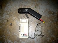
I borrowed the clamp on AC/DC amp probe from work and did a quick test. Not super scientific, since I had a hard time loading the motor enought to get full amps.

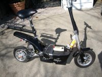
I have my trusty analog meter on the battery wire, and the clamp on over one of the three phase wires. For maximum current draw, I was starting from a dead stop on an 18% grade. With the brakes on in some cases.

The maximum "multiplication effect" seemed to be around 25 amps input, where I was measuring around 100 amps output.

As the motor picked up speed and the duty cycle increased, the output/input ratio dropped.

For a 35 amp limited controller, the motor will see a little over 100 amps at low throttle settings.

The highest reading I could get was around 170 amps with my 90 amp input limit. I was not using a meter with a min / max memory, so the readings had to stay there a second or so to read them.
 

Attachments

  • Current test 2.jpg
    Current test 2.jpg
    64.2 KB · Views: 6,031
  • Current test 1.jpg
    Current test 1.jpg
    68.8 KB · Views: 6,031
This certainly explains why motors run at low rpms heat up so quickly. All that current still has to operate within an "efficiency regime" that is very poor, so you are really turning your motor into a "space heater" when you run at low rpms like that. (lot's of waste for little return)

It definitley makes me want a controller that eliminates this effect. (and gears to embrace the "good parts" of the powerband)

:arrow: Those results are dreadful... :cry:
 
Good news!
Explains why i can ride my mbike in stores at 1-3 mph and only draw 1 to 2 amps input, even from a stop.(no load amps, wheel up is 2.8 full)
Sure beats a rheostat!

safe doesn't realize wattage doesn't go up because volts are down.

explains why my fets are rated 80a on a 35a limit. they are not generous at all. it is NEEDED!
 
Thanks for that Fechter. I didn't realize the current multiplying effect was so big.

So how would that apply to an Alltrax with current limit set at 200A?
Would the motor side actually see much higher currents there as well, but for such short periods that it's not a problem?

Just thinking about my fuse and breaker ratings.
 
Yes, I would expect the same thing to be true for a brushed controller. If you want to put a fuse between the motor and controller, it will need to be about 3x what the input is. With a brushed setup, I don't see any advantage to fusing the output as long as the input is fused. I'm not sure if the Alltrax current limit is based on the input or output. The Alltrax guys would know. It's possible to set up the limiter either way.

Most cheap brushed controllers limit the input current.

At very low speeds, even though the current is high, the motor heating does not seem to be as much as one might expect. I guess you don't normally stay in that operating area very long. Also the power is low at low throttle settings.

After about 5 minutes of testing at max current, my motor was barely warm. I was going very slow.

One thing this test does indicate is the resistance of the wiring from the motor to the controller should be as low as possible. Keep the wires as short and fat as possible. Since resistance losses are I2R, if you have 3x the current on the output, the losses would be like 9x more for a given size of wire.
 
fechter said:
At very low speeds, even though the current is high, the motor heating does not seem to be as much as one might expect. I guess you don't normally stay in that operating area very long. Also the power is low at low throttle settings.

But at full throttle and low rpms the motor DEFINITELY becomes a "space heater". I found that out when I tried to climb a hill in a gear that was too tall. The result was a motor that was literally beginning to smoke.

Watts = Volts * Amps

So it seems to me that if the low rpm Volts are held constant and the Amps are given a "multiplication effect" then any heat related effect that is tied to current would go up in direct proportion to the current at that given rpm.

After all.... the motor's physical properties do not change because of controller manipulations. If a motor is physically designed to operate best at say 3000 rpms and you run it at 1000 rpms instead there's no way (that I can see) that you would avoid the physical efficiency limitations inherent to the motor under those conditions.

People tend to "want to believe" what suits their fancy many times. If someone is using a fixed hub motor then they would naturally seek "magical answers" to their performance issues.


:arrow: Can ANYONE explain ANY reason why low rpms with the PWM "effect" would NOT comply with the general low efficiency regime?

Honestly, I'd like to hear the "magical answer" that makes it seem like a good idea. As it is now all I want is to eliminate the PWM "effect" because it encourages "bad behavior" that produces heat and also increases torque in areas that gears could do a better job at controlling by placing the rpms elsewhere. For the "geared bike" there is absolutely no reason to support the PWM "effect" because there are no benefits at all to having it...
 
With a brushed setup, I don't see any advantage to fusing the output as long as the input is fused.

Alltrax actually recommend putting a fuse on the ouput side in direct drive applications. I don't know enough to argue with them. After your tale of having your arms almost torn from their sockets when a controller failed open I'm going for the belt and braces approach. I'll start with a 150A fuse and keep increasing it until it stops blowing :D
 
safe
u r a slow learner.
maybe Leeps will try again but i sure won't.
it has already been explained.
 
From Wikipedia:

Force (or Torque) is Current.
Speed (or Movement) is Voltage (or Frequency).
Electrical Loss (or Heat) is Current Squared.
Power is the product of Speed (or Voltage) and Force (or Current).


From these equations I simply cannot see how you get "good power" from the PWM "effect". If the current is doubled then you would expect the square of that in heat as a result. There's no mention of voltage in heat buildup... so unless you know of some "magical physics" I just don't know how you avoid heat buildup when you increase current. (no matter how it's done)

:arrow: It's obvious that low rpms produce heat... we all experience this... so I'm at a loss why you would not acknowledge that heat and low rpms are related.

I'm not saying there isn't more TORQUE at low rpms because of the PWM "effect". I'm just saying that it isn't "free" because you pay very dearly in terms of heat buildup. This is MUCH more noticeable on small motors and on a big motor you might not need to worry about it very much because the time spent in getting through the low rpms is short enough that you don't have the time to build up the heat. (and you always are ABLE to get through, which for a small motor and a big hill is not always the case) You guys are talkiing about 150 Amps.... that's not bicycle territory that's PMG132 and Etek territory. Those of us operating within the "750 Watt legal limit" MIGHT be more sensitive to these issues... (we can actually feel the results much more closely because we are closer to the limits of the motor all the time)
 
Matt Gruber said:
it has already been explained.

Not on this forum to my knowledge. I've seen many postings extolling the virtues of the extra current that the PWM "effect" achieves at low rpms, but I've never seen anyone "explain away" heat related issues with increased current that result.

:arrow: To my knowledge current and heat are related in that heat is the square of current no matter how you achieve the current.

It's the current and not the voltage that actually burns up your motor.


And from this you come to realize that the "best power" comes as a result of the highest voltage and the lowest current... which we know to be true because that's how they set up the NEDRA classes based out of respect for these core principles... the PWM "effect" is creating a situation of high current and low voltage... so how the heck can that be any good?
 
fechter said:
Yes, I would expect the same thing to be true for a brushed controller. If you want to put a fuse between the motor and controller, it will need to be about 3x what the input is...

Fechter, I had a fuse in my motor loop with my Numo/Altrax setup.

I ran it detuned at 120amps. Both fuses were 175 amps.

There are certain parameters that a fuse is designed to blow, such as time and overcurrent.

Fechter, I don't understand what you are seeing, could you explain what's going on? Could it be the increased resistance of the warm wire needing more current?

Could the controller have bad output filtering/capacitor sending pulses to the motor coils that have enough time to dissipate and send back EMF to the MOSFETS and diodes?

[I thought, it probably cost me an ohm, but I wanted the controller to outlive the motor, should a commutator segment short/bridge or something. I wanted to blow the fuse in case of a WFO.]
 
Matt Gruber wrote:
it has already been explained.


Not on this forum to my knowledge.

It's been explained. As I recall, the reason went to usually not using all the motor side amps available, except for a very brief spurt during acceleration, or a prolonged burst on a steep hill where, without the PWM amp multiplier, the motor wouldn't climb the hill at all. Gearing doesn't change anything as you've noted many times,
I found that out when I tried to climb a hill in a gear that was too tall. The result was a motor that was literally beginning to smoke.
because as you gear down to take the load off the motor, you slow down to the point where, like if the PWM effect was absent, the motor runs cooler (more efficiently) but won't climb the hill at an acceptable rate. In this sense the variable PWM multiplier is no different than having many gears available to choose from -- choose the best throttle/current setting, choose the best gear to run the motor as efficiently as can be above the minimum acceptable speed.
 
Motor heating is a function of current only. The current the motor draws depends on loading (torque) and the no-load current of the motor.

If there's not enough voltage going to the motor to overcome its back EMF, it won't be able to draw as much current (or produce as much torque). This happens as the motor rpm increases.

If the motor is loaded to the point where it draws too much current, it burns up. Proper setting of the current limit will prevent this. Regardless of whether the limiter is sensing the input or output current, the PWM current boosing effect happens anytime the duty cycle is less than 100%.

Brenda, the motor / controller combination funcitons much like a buck switching power supply. At partial throttle, energy is stored in the magnetic field of the windings. When the switch opens, the field collapses and the current is circulated by the freewheel diode.

It's similar to the way a transformer works with AC. Since the controller is not dissipating a significant amount of power, then the power input = power output (Ok, there's a 5% or so loss, mostly in the motor).

Let's say, for example, you have 48v battery feeding 20 amps into the controller. 48 x 20 = 960w. At reduced throttle, the output voltage will be less, let's say 24v at half throttle, so you would get 40 amps into the motor, since none of the watts are getting "lost".
 
fechter said:
If the motor is loaded to the point where it draws too much current, it burns up. Proper setting of the current limit will prevent this. Regardless of whether the limiter is sensing the input or output current, the PWM current boosing effect happens anytime the duty cycle is less than 100%.

Yes, a very low current limit that matches the efficiency peak value is "ideal" and results in the minimum "foundation" on which heat is generated. (every motor heats, but some worse than others)

But all things being EQUAL...

The PWM "effect" given the same motor and the same current limit will create MORE heat than a comparable "fixed current" controller. (theoretical in our world because PWM is the standard... imagine a simple direct battery source setup of some type like the "battery throttle" idea from some time ago)

:arrow: Does my point get though on this? That current is the "enemy" and no matter how you phrase the question it always has an additional heating effect when you draw more current. Since the PWM "effect" draws more current it therefore translates into MORE HEAT compared to the theoretical "ideal" of less current for the same voltage at low rpms.

Does this make sense or not?

If you want to get up a hill you can either ADD more energy (to a bigger motor) and get more torque and zip up the hill at high speed (so that you don't fall out of your powerband) OR you can gear down and use less current and produce less heat and still get up the same hill but at slower speed. If the small motor tries to "cheat" with the PWM "effect" it produces a "space heater" that wastes energy and produces lot's of heat.

So the choices are:

:arrow: 1. Big Power (so that you can avoid low rpms altogether)

:arrow: 2. Many Gears (so that you can avoid low rpms altogether)

But the low rpm PWM "effect" is almost more of a problem than a blessing because all that extra current produces excessive amounts of heat... (and it entices someone to use their low rpm torque... just because they can)
 
xyster said:
...for a very brief spurt during acceleration, or a prolonged burst on a steep hill where, without the PWM amp multiplier, the motor wouldn't climb the hill at all.

:arrow: That makes sense.

If you have a "Big Motor" that can pull you up any hill then the PWM "effect" is used to simply "get you out of the bad stuff" at low rpms and get you up to the higher rpms where the motor can run better. I get that... and on a "Big Motor" it would work fine.

On the "Small Motor" though where you often have no chance of making it up the hill at all unless you significantly gear your bike down then things are different. If you are able to go up a hill at 10 mph when your top speed might be potentially 50 mph then there's a huge gap between the two extremes.

This all gets back to what appears to be the "Geared Verses Fixed Gear Power Ratio" that seems to settle in at about 3 to 1. If you can get a motor that is of about three times the power of the geared bike you can run a fixed gear and get the same results.
 
Great experiment,

I'm totally confused by the results :D Fetcher, are you sure your meter is not reading very high amp spikes created by the pwm switching rather than an 'average current'?

I thought I PWM was really simple, basically just a very fast switch: As the throttle is turned down. The battery voltage doesn't change(ignoring sag). The motor see's a lower voltage as it sees the average voltage of the switching. The current to the motor is also lowered because no amps get through when the swich is off. The bike slows down.


fechter said:
Let's say, for example, you have 48v battery feeding 20 amps into the controller. 48 x 20 = 960w. At reduced throttle, the output voltage will be less, let's say 24v at half throttle, so you would get 40 amps into the motor, since none of the watts are getting "lost".

I don' understand whats happening in the example. At half the throttle the my bike only has half the power output. But in the above example, total watts are the same. So what is happening to the missing energy, is it just wasted as heat?

As a real world example I remember one of knoxie's vids where he put 40 amp fuses on the phase wires. This was for the Puma motor witha 35 amp controller. If I remember right he did report problems with fuses melting but not instantly the bike seemed to run ok at least for a while.
 
This page http://www.4qdtec.com/pwm-01.html on the 4qd website explains the basics well.

Here's an extract (you'll have to imagine the pictures):

Consider the waveform above. If the motor is connected with one end to the battery positive and the other end to battery negative via a switch (MOSFET, power transistor or similar) then if the MOSFET is on for a short period and off for a long one, as in A above, the motor will only rotate slowly. At B the switch is on 50% and off 50%. At C the motor is on for most of the time and only off a short while, so the speed is near maximum. In a practical low voltage controller the switch opens and closes at 20kHz (20 thousand times per second). This is far too fast for the poor old motor to even realise it is being switched on and off: it thinks it is being fed from a pure d.c. voltage. It is also a frequency above the audible range so any noise emitted by the motor will be inaudible. It is also slow enough that MOSFETs can easily switch at this frequency. However the motor has inductance. Inductance does not like changes in current. If the motor is drawing any current then this current flows through the switch MOSFET when it is on - but where will it flow when the MOSFET switches off? Read on and find out!


Consider the circuit above: this shows the drive MOSFET and the motor. When the drive MOSFET conducts, current flows from battery positive, through the motor and MOSFET (arrow A) and back to battery negative. When the MOSFET switches off the motor current keeps flowing because of the motor's inductance. There is a second MOSFET connected across the motor: MOSFETs act like diodes for reverse current, and this is reverse current through the MOSFET, so it conducts. You can use a MOSFET like this (short its gate to its source) or you can use a power diode. However a not so commonly understood fact about MOSFETs is that, when they are turned on, they conduct current in either direction. A conducting MOSFET is resistive to current in either direction and a conducting power MOSFET actually drops less voltage than a forward biased diode so the MOSFET needs less heatsinking and wastes less battery power.

You should see from the above that, if the drive MOSFET is on for a 50% duty cycle, motor voltage is 50% of battery voltage and, because battery current only flows when the MOSFET is on, battery current is only flowing for 50% of the time so the average battery current is only 50% of the motor current!
 
In my example case, 20 amps input would be at half throttle.
As the throttle is decreased, the input amps would decrease also.

Regardless of throttle setting, the input power and output power are nearly equal.

I'm pretty sure my readings are accurate, other than they were bouncing around quite a bit. An analog meter would have been better.

In Knoxie's case, the current on the output is probably over the fuse rating every time he accelerates, but the time is too short to blow the fuse most of the time. A 40amp fuse will handle 40 amps continuously. It will probably handle quite a bit more than 40 for a second or so.

In a PWM setup, the current in the motor does not stop when the switch opens. The current is sustained by the collapsing magnetic field going through the freewheel diode.

There's a fairly good description of it here:
http://www.4qdtec.com/pwm-01.html
and here:
http://www.powerdesigners.com/InfoWeb/design_center/articles/DC-DC/converter.shtm

Whether you have gears or not, you still need to start up from a stop and be able to vary your speed.


NickF23 said:
Great experiment,

I'm totally confused by the results :D Fetcher, are you sure your meter is not reading very high amp spikes created by the pwm switching rather than an 'average current'?

I thought I PWM was really simple, basically just a very fast switch: As the throttle is turned down. The battery voltage doesn't change(ignoring sag). The motor see's a lower voltage as it sees the average voltage of the switching. The current to the motor is also lowered because no amps get through when the swich is off. The bike slows down.

fechter said:
Let's say, for example, you have 48v battery feeding 20 amps into the controller. 48 x 20 = 960w. At reduced throttle, the output voltage will be less, let's say 24v at half throttle, so you would get 40 amps into the motor, since none of the watts are getting "lost".

I don' understand whats happening in the example. At half the throttle the my bike only has half the power output. But in the above example, total watts are the same. So what is happening to the missing energy, is it just wasted as heat?

As a real world example I remember one of knoxie's vids where he put 40 amp fuses on the phase wires. This was for the Puma motor witha 35 amp controller. If I remember right he did report problems with fuses melting but not instantly the bike seemed to run ok at least for a while.
 
Malcolm said:
You should see from the above that, if the drive MOSFET is on for a 50% duty cycle, motor voltage is 50% of battery voltage and, because battery current only flows when the MOSFET is on, battery current is only flowing for 50% of the time so the average battery current is only 50% of the motor current!

:arrow: Which is not what Fechter actually measured... (or believes to have measured)

The PWM "effect" is weird... it seems to be "real" in that you do seem to get a little added torque in areas where it normally would not be. It gives advantages to the hub motor that normally would be incapable of doing much at such low rpms, but it complicates matters for people with gears because it creates a non-linear torque curve. It's the no-linear nature of the PWM "effect" torque that bothers me more than the heat problems. The heat problems can be avoided by simply staying out of low rpms whenever possible and if you do on occasion dip down their it's normally "okay". The problem with geared systems is that those "occasional" dips into the low rpms can literally "pop" your gears all at once. There is a huge "pike" at the low rpms and that translates into trouble for the geared bikes.... one bad shifting decision and the hub might break on you...
 
fechter said:
There's a fairly good description of it here:
http://www.4qdtec.com/pwm-01.html
and here:
http://www.powerdesigners.com/InfoWeb/design_center/articles/DC-DC/converter.shtm

dis_f4.gif


:arrow: Output Voltage vs Current

This chart "seems" to apply, but I'm not clear what "d" stands for... "duty cycle"?


Also, is this "parabolic shape" (based on the Y-axis) of how the PWM "effect" applies to current correct? I've been using a very crude linear analysis that might be overstating the "negatives" of PWM. Hopefully I've been overly cautious... is this true? Does the PWM "effect" follow like in the chart above?
 
4.1 Flyback Converter

The flyback converter can be developed as an extension of the Buck-Boost converter. Fig 14a shows tha basic converter; Fig 14b replaces the inductor by a transformer. The buck-boost converter works by storing energy in the inductor during the ON phase and releasing it to the output during the OFF phase. With the transformer the energy storage is in the magnetisation of the transformer core. To increase the stored energy a gapped core is often used.

http://www.powerdesigners.com/InfoWeb/design_center/articles/DC-DC/converter.shtm

Fechter, you have said in the past that most PWM controllers actually work as a "Flyback Converter" because they store up energy between pulses. This increases the PWM "effect" because it means there is more energy "built up" and ready to go when needed.

:arrow: Is this true?
 
No, I said they work like a buck converter.
d is duty cycle.

We'd normally be way over the right on the graph.

Keep in mind that the motor itself is the inductor in a motor controller setup. Anytime you start adding more inductors, transformers, etc, it usually increases losses.
 
safe said:
The problem with geared systems is that those "occasional" dips into the low rpms can literally "pop" your gears all at once. There is a huge "pike" at the low rpms and that translates into trouble for the geared bikes.... one bad shifting decision and the hub might break on you...


I'm not sure PWM's effect on torque is a threat there... low RPMs will likely inspire the operator to downshift, which, on one hand adds torque to the hub (a bigger sprocket is just a bigger lever); but on the other hand the force is spread over a longer period of time. In addition, the low RPMs at the motor will not carry enough rotational momentum to adversely effect the hub & wheel, because the motor doesn't have much mass.

It's the shock-loads that kill hubs, not PWM. Like somebody said earlier, breaking a hub requires either an instant application of torque: like a clutch-drop with a heavy flywheel; or the slow application of stump-pulling gearing like 50:1 on a mass so great that it may as well be a stump.

You ain't that fat, and yer gears ain't that low.


8)
 
TylerDurden said:
You ain't that fat, and yer gears ain't that low.

It really depends on what your hubs ability to stand torque really is. The only number I've ever seen published describing a "maximum" for a hub is the Rohloff at 100 Nm. Is that a low number since they have 16 gears and most of them are below 1 to 1? Right now my Lead Acid bike is running peak torque of about 132 Nm at the hub on a freewheel and I'm now nearing 700 miles on the bike. The previous "cheapo" hub broke, but I had thrown a chain in between the hub and frame and tried to crank it at full power, so that probably caused that failure. I've even had plenty of sloppy and overly aggressive shifts on the new freewheel and no problems. (it's a Shimano and seems well built)

:arrow: So it's really hard to know...

You almost have to take the testing into your own hands and simply try stuff and see what works and what doesn't. It might turn out that many hubs can handle over 200 Nm before they break.

But it's the "peak" that matters... and the highest "peaks" do tend to occur during things like shifting.... so maybe hub torque and PWM is overblown as an issue? Maybe it's worth it to just "not care" and see what happens... (it might cost me a hub, but then I'll at least know for sure)
 
Thanks for the links Fetcher (and Malcolm). I had a good read about inductors. sometimes, I like to think I'm learning more :D

I still find the current multiplication you were seeing very surprising. I have 50 amp fuses on two of the phases of my kollmorgen motor with a 26 amp controller at 48 volts. If the current multipliation is a factor of 3 or 4 as a continous output rather than pulses at say 1/4 throttle I surprised they haven't blown by now.
 
Back
Top