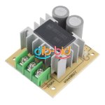
Combine volt amp and Ah meter for USD $15

Very cute and probably true, ykick! These demons have gotten a couple of electronic devices I own, including the Ping pack that I had to rebuild. The other products, not so good. My younger grandson managed to drop his Zune MP3 player in the............... (wait for it).......................................toilet. Yep and surpruze it doesn't work now. He is a teenager which explains everything, I'm sure. You need a special 3 blade screwdriver to open the darn thing.
otherDoc
 
It's awesome that it does 48V, I've seen plenty operating on only 12 or 24V.
The 20A will most likely already be with a shunt. Most 12/24V amp/watt meters require a shunt; basically a calibrated piece of metal, with a small resistance.
Say you have 100A of current,and use a shunt (piece of metal), the amp flow over the meter would be 1A, and 99A go through the shunt.
The meter will essentially be measuring 1A instead of 100. quite often they are off in decimals, or even in quarters of a number (depending on what shunt you install, it is for instance possible that 75A will go through the shunt, and 25A through the meter. In that case you'd have to multiply the value by 4, to read out the correct value).
But correct shunt values should be mentioned on the specs sheet of the device!

Too bad I don't like installing a shunt, it'd be way nicer for it to operate without, but on my ebike (48V, 20A), the bike can have upto a 40A powerdraw (700W motor). Too much for the meter to handle!

What voltage does it need for the LEDS?
Does it need a separate voltage (usually they need either a separate 12 or 5V supply for the leds)
 
ProDigit said:
It's awesome that it does 48V, I've seen plenty operating on only 12 or 24V.
The 20A will most likely already be with a shunt. Most 12/24V amp/watt meters require a shunt; basically a calibrated piece of metal, with a small resistance.
Say you have 100A of current,and use a shunt (piece of metal), the amp flow over the meter would be 1A, and 99A go through the shunt.
The meter will essentially be measuring 1A instead of 100. quite often they are off in decimals, or even in quarters of a number (depending on what shunt you install, it is for instance possible that 75A will go through the shunt, and 25A through the meter. In that case you'd have to multiply the value by 4, to read out the correct value).
But correct shunt values should be mentioned on the specs sheet of the device!

Too bad I don't like installing a shunt, it'd be way nicer for it to operate without, but on my ebike (48V, 20A), the bike can have upto a 40A powerdraw (700W motor). Too much for the meter to handle!

What voltage does it need for the LEDS?
Does it need a separate voltage (usually they need either a separate 12 or 5V supply for the leds)

The 90V/20A one originally found by NeilP (here: http://cgi.ebay.com/ws/eBayISAPI.dll?ViewItem&item=180830130528#ht_3217wt_1228) has an internal shunt, like the Turnigy and other RC wattmeters.

The alternative programmable ones that jpgey has linked to (here: http://stores.ebay.com/Elite-element/Programmab-le-Combo-Meter-/_i.html?_fsub=3083751012&_sid=897140872&_trksid=p4634.c0.m322) need an external shunt, but this is included. The non-programmable versions (here: http://stores.ebay.com/Elite-element/Dual-Display-Combo-meter-/_i.html?_fsub=3083749012&_sid=897140872&_trksid=p4634.c0.m322) also need an external shunt, but in this case the shunt is extra and not included.

Both are powered by the supply, again like the Turnigy and similar units, so don't need any separate supply for the display.
 
thank you,
but how is it that the meter can tap off the main power supply, as the voltage can be anywhere from 12 to 90V?
It has an automatic voltage regulator within for the LEDs? I suppose it must be!
 
Really happy with mine, shows me that the BMS is doing its job at the end of the charge. The Turnigy one used to stop measuring below 5W or so... this one goes down much lower.
 
ProDigit said:
thank you,
but how is it that the meter can tap off the main power supply, as the voltage can be anywhere from 12 to 90V?
It has an automatic voltage regulator within for the LEDs? I suppose it must be!

All these wattmeters have an internal voltage regulator, as it's needed to ensure that the µcontroller that does the measurement and drives the display has a constant and regulated voltage.
 
Attention: This device cannot check reverse polarity, then no regen information !
CA can check reverse polarity and Ah you get back !
 
jpgey said:
Attention: This device cannot check reverse polarity, then no regen information !
CA can check reverse polarity and Ah you get back !

still good as a charger watt meter, who wants a bike with 20a discharge anyway?
 
jpgey said:
Attention: This device cannot check reverse polarity, then no regen information !
CA can check reverse polarity and Ah you get back !

None of the other wattmeters available, such as the Turnigy or any of the various models of RC meters, can do this, AFAIK, as they all use a low side shunt to measure current, as these meters do. The CA is the exception, as Justin specifically designed it to be bidirectional so it could be used for charge and regen monitoring on ebikes, not something that the users of simple wattmeters usually need.
 
Hell, for that price you could just use two of them if you really want regen information.
This really looks ideal for adding to a charger.
 
fechter said:
Hell, for that price you could just use two of them if you really want regen information.
This really looks ideal for adding to a charger.

It would not work.
Since they are watt meters, to measure volts, they will have to be placed in parallel, to measure amps, they will have to be placed in series.
Best you can do is use a diode bridge to rectify the current, but you'll be losing some over the bridge.
 
ProDigit said:
fechter said:
Hell, for that price you could just use two of them if you really want regen information.
This really looks ideal for adding to a charger.

It would not work.
Since they are watt meters, to measure volts, they will have to be placed in parallel, to measure amps, they will have to be placed in series.
Best you can do is use a diode bridge to rectify the current, but you'll be losing some over the bridge.

It'll work just fine as fechter says, just the same way the other RC type wattmeters on the market work for doing this.

The unit measure both supply voltage (across the right hand pair of terminals looking at the rear) and current (presumably via a low side internal shunt across the right hand - inputs and the left hand - input). The right and left hand + and left hand + terminals will probably be a pass-through, just like the Turnigy and other RC wattmeters.

It calculates watts from measuring voltage and current, and capacity (Ah) by measuring current and time elapsed since power on.

Why wouldn't this work just perfectly for a charger?
 
A couple of these arrived in the post today. I've done a quick test and they seem OK, reasonably accurate and easy to use. Like the Turnigy, Watts up and others this unit has the shunt in the negative connection, the two positive connections on the back are just a loop-through. Wiring up is easy, input power goes to the two input connections, output comes from the two output connections.

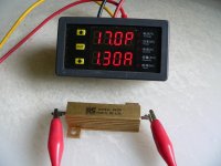
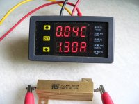
The display starts with the upper display showing volts and the lower display showing amps. It's reasonably accurate, about as good as plus or minus one digit of the display resolution, which is to either one or two decimal places. The arrow buttons cycle each display through a sequence, of displaying volts, amps, watts, elapsed time since power on and capacity (amp hours) since power on. Each button controls the adjacent display, so the lower (down arrow) scrolls the lower display sequentially and the upper button (up arrow) scrolls the upper display. I haven't yet worked out what the "OUT" button does!

Here are a few photos with me scrolling the upper display through three of the selections. The unit is running off a bench supply and just feeding 10 ohm load resistor for testing:

View attachment 5

P A small.JPG

C A small.JPG


The thing comes with no manual, paperwork or whatever, but seems pretty intuitive to use (except for the "OUT" button................).

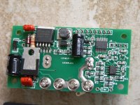
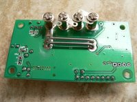
I've taken one apart and it looks pretty generic. The display board has some demultiplexing to drive the LEDs from just a few of the pins from the µcontroller (which looks to be an Atmel device). The analogue front end uses a dual CMOS op amp to measure the voltage drop across the shunt. There's a switch mode power supply, using a Simple Switcher, so it should be reasonably OK over a wide range of supply voltages. There are pads on the board marked "Ext Supply", so my guess is that you could choose to independently power it by connecting to these and maybe removing the adjacent solder bridge. The three tactile switches on the display board all go directly to pins on the µcontroller, which means the mysterious "OUT" button must do something...............

View attachment 2

PCB front.JPG

PCB rear.JPG
 
Cool. I've ordered one and I'm looking forward to reverse engineering it.
The datasheet for the LM2596s indicates a maximum input voltage of 45v.
The external power input may make it possible to use a separate dc-dc converter and operate at higher voltages.
 
fechter said:
Cool. I've ordered one and I'm looking forward to reverse engineering it.
The datasheet for the LM2596s indicates a maximum input voltage of 45v.
The external power input may make it possible to use a separate dc-dc converter and operate at higher voltages.

The spec for this unit is 90 V, 20 A, so it looks as if they do something to limit the voltage to the reg before hand, a bit like the Xiechang controllers. Quescient current is around 15 mA, BTW, so not to greedy and lower than I would have thought for an LED display. It's not ultra-bright and probably isn't daylight readable, but it's OK indoors.
 
is it possible to mod this for 100v even if the voltmeter doesnt work, and use it as an ah meter?
 
ian.mich said:
is it possible to mod this for 100v even if the voltmeter doesnt work, and use it as an ah meter?

Maybe. If you fitted a resistor in series with the positive feed (run it in three wire, rather than four wire, mode) of around 1k5 ohms, 1/2 watt. This would drop the input voltage by around 22 V, and allow the meter to work safely at 100 V. The current would still be measured accurately through the negative terminals, and the Ah used should still read OK, but the voltage and power displays would be way out.

You could set one display to read current and the other to read Ah, which might be useful, but you'd need to press the buttons to get each display to this setting every time you power the unit on.
 
ian.mich said:
is it possible to mod this for 100v even if the voltmeter doesnt work, and use it as an ah meter?
Or you could just use the unmolested meter on 1/2 of your pack. The current and ah would remain the same. Volt and power would be 1/2 of the actual values.
 
Arr at last some action on this one, Im watching this closely my hope is a hack for 120v/70 amp, and a clean remote shunt install, like done to the turnigy metre.
And hope it doesnt lose any ah accuracy when it heats up under load
 
Dc=DC Converter.jpgThe same seller has some NICE DC-DC converters
15-50 VDC in !2V or 5v output@3A

I bought tw0 for $3.50 each shipped FREE. It arrived with in 3 weeks

Works GREAT and with no solder needed. 3 screw terminal
 
Nice,
What are the peak amps it can handle?

The battery pack I currently have in my bike has 20Ah, 40Ah peak.
Wouldn't want the device limiting the current flow, or getting overbalasted.
 
ProDigit said:
Nice,
What are the peak amps it can handle?

The battery pack I currently have in my bike has 20Ah, 40Ah peak.
Wouldn't want the device limiting the current flow, or getting overbalasted.

The ones I bought that are the ones originally linked to at the start of this thread (there are other similar ones around) and are rated at 90 V, 20 A. The higher current ones are available from another vendor (also linked to earlier in this thread) and use an external shunt.

Looking at the shunt in the ones I have, it seems able to take more than 20 A (it's pretty similar in resistance wire gauge and length to the shunt in a 40 to 50 A controller), but the meter probably won't read anything over 20 A, making the current, power and Ah display read in error if higher current was drawn.

If you want to go over 20 A then I'd suggest getting one of the ones with an external shunt. Also, if you want to fit it to the bike, rather than use it to monitor battery charging, then it's not likely that you'll be able to read the display well in bright light, again as I mentioned above.

These units are pretty much ideal as a simple meter to build in to a charger or bench power supply, but less useful for putting on a bike, in my view.
 
Back
Top