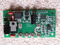
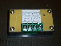
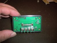
Combine volt amp and Ah meter for USD $15

My meanwell bulk charger now has an awesome display. I think these are a great little unit.
Voltage seems quite accurate for my purposes. And it does Ah and Power which I didn't realise when I bought it.

Holding the OUT button for a second it does go into some sort of setup menu, I haven't played around with it.
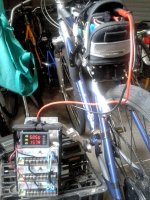
charger display.jpg
 
Would anybody with one of these be so kind as to take a pic of the front-side of the logic board with the Atmel microcontroller(s)? I'm interested in reversing/reimplementing the firmware to make a poor man's CA for my spare-ebike that is not worthy of the genuine article. It'll be a few weeks before I get my meters and I want to get a head start on understanding the chips :p . At the very least, I could tap the UART pins and bring out a serial port for logging or meter queries. It'd be nice to be able to plug an aux data cord from the meter into a smart charger so one could "unwind" the watt-hour count, Ah for Ah. The hardest part on a new firmware would be to get the LCD mux figured out, but I think the through-hole construction will make the design simple to trace. For $15, it's a throwaway part that safe to hack on!
 
Received mine today:
dc-dc_reader.jpg


Can I use it with my 66V charger? I'll connect the input from the charger and output to the battery, is it like this?

And no problem with the 60V limit?
 
cwah said:
Received mine today:

Can I use it with my 66V charger? I'll connect the input from the charger and output to the battery, is it like this?

And no problem with the 60V limit?

For sure.
 
TheWizard said:
Would anybody with one of these be so kind as to take a pic of the front-side of the logic board with the Atmel microcontroller(s)? I'm interested in reversing/reimplementing the firmware to make a poor man's CA for my spare-ebike that is not worthy of the genuine article. It'll be a few weeks before I get my meters and I want to get a head start on understanding the chips :p . At the very least, I could tap the UART pins and bring out a serial port for logging or meter queries. It'd be nice to be able to plug an aux data cord from the meter into a smart charger so one could "unwind" the watt-hour count, Ah for Ah. The hardest part on a new firmware would be to get the LCD mux figured out, but I think the through-hole construction will make the design simple to trace. For $15, it's a throwaway part that safe to hack on!

Sorry, I missed this request earlier. Here's the best I can do:

Meter PCB front view.JPG
 
Well, I got mine today :wink:

Interesting how the design changes in just a couple of weeks. Mine has a terminal block for the wire connections. This looks like a nice improvement.

I wanted to know how the voltage regulator worked, so did some poking around. It uses a simple zener/transistor linear regulator ahead of the simple switcher chip. The pre-regulator is set for about 40V.
The current draw going into the simple switcher drops to about 10mA by the time the input voltage reaches 40V. This keeps the heat on the linear regulator down to a reasonable level.

The output of the simple switcher was measured at 3.23V. The circuit runs off this.

It starts to read accurately with an input voltage of around 10V.

There is a diode on the input that protects against reverse input connections (excellent idea).

Using less-than-optimal test equipment, I measured the shunt at around 4mOhm. This means at 20A current, the shunt will be dissipating about 1.6W. The shunt wires will get pretty warm, but I think it should be OK.

The digital displays are auto-ranging, so if the value is greater than 9.99, the decimal place moves.

Mine came with no instructions either. I'll have to work on transrating the .pdf.
Voltmeter 1.jpg
Voltmeter 2.jpg
 
Ypedal said:
mine arrived last friday, i got the brass bolt type not the one's fechter got.. i plan to solder wires direct to the board anyway.. have not powered it up yet.


I also got the same...

will probably use it for my Zero charger

Doc
 
fechter said:
Well, I got mine today :wink:

Interesting how the design changes in just a couple of weeks. Mine has a terminal block for the wire connections. This looks like a nice improvement.

Got the exact same one in the mail today. Two of them actually. Tested it on a computer fan and it seems to work well. Might order a few more at this price just for shits n giggles
 
I'd like to connect my mini AH/Wattmeter to the charger output:
20120721_001452.jpg


But the output plug seems to have 3 connectors:
20120721_001327.jpg


Any idea how do I insert 3 connectors to the 2 input from this little AH/Wattmeter?
 
You want to measure from the side that goes into the battery. There's no 3rd (prong female) grounding 3rd wire on the two wire DC side that plugs-in to charge the battery. (Unless there is a spark prevention pre-charge wire at the end.) Regardless, you just use the +/- two wires on that DC charge side where you want the meter to measure. If the DC side charging wire is too big a diameter wire to connect, then use terminal connectors you crimp the big wire on to, or buy & use 4 very short pieces of smaller diameter wire with terminals already crimped on for you to connect to the meter's +/- terminals for input/output & solder the 4 wire ends to the respective fat wire.

If your setup is using a BMS, then I suppose the 3rd wire might serve some BMS function if it charges/balances through that too. In that case, you need to get info on the BMS to understand the wiring issues.
 
I've put the input wire to the charger and the output to the battery:
wattmeter_burnt.jpg


All burnt after few seconds from the charger connected to the battery, got my floor burnt too.

What did I do wrong? :(
 
yeah i would be careful about how they set up that wattmeter, I would personally solder the wires into the board then cover with silicone.
 
Just received it and it's already down :(

Going to protect it with silicone tape then. Is this one ok?
http://www.amazon.co.uk/Black-Self-Amalgamating-Waterproofing-Connections/dp/B000KH9UHM/ref=pd_cp_ce_0
 
Thanks for that picture. I finally got mine and took a closer look. The MCU is an STM8 and theres a TI 272c op-amp attached to it.

http://www.st.com/internet/mcu/product/215113.jsp

looks like I could use a versaloon board to program the chip using 4-pin SWIM (which might be what that unpopulated 4-pin header is for next to the ST chip on the PCB...)

http://www.versaloon.com/index.html

I think I'll try using this meter for its intended purpose for awhile, before I try breaking it :)

Jeremy Harris said:
TheWizard said:
Would anybody with one of these be so kind as to take a pic of the front-side of the logic board with the Atmel microcontroller(s)? I'm interested in reversing/reimplementing the firmware to make a poor man's CA for my spare-ebike that is not worthy of the genuine article. It'll be a few weeks before I get my meters and I want to get a head start on understanding the chips :p . At the very least, I could tap the UART pins and bring out a serial port for logging or meter queries. It'd be nice to be able to plug an aux data cord from the meter into a smart charger so one could "unwind" the watt-hour count, Ah for Ah. The hardest part on a new firmware would be to get the LCD mux figured out, but I think the through-hole construction will make the design simple to trace. For $15, it's a throwaway part that safe to hack on!

Sorry, I missed this request earlier. Here's the best I can do:

 
cwah said:
I've put the input wire to the charger and the output to the battery:

All burnt after few seconds from the charger connected to the battery, got my floor burnt too.

What did I do wrong? :(

Bummer. Looks like the output to the battery shorted & burnt holes where the short occurred. Wires or mounts must have touched where it burned through. (This assumes you didn't reverse the wiring & connect to wrong terminals. That would heat & burn fast, imo.)

Not a very good design allowing for wide spacing or insulated dividers between the wiring connections. :roll:
 
cwah said:
Just received it and it's already down :(

Going to protect it with silicone tape then. Is this one ok?
http://www.amazon.co.uk/Black-Self-Amalgamating-Waterproofing-Connections/dp/B000KH9UHM/ref=pd_cp_ce_0

try silicone glue, this one
http://www.permatex.com/products/automotive/adhesives_sealants/sealants/auto_Permatex_Clear_RTV_Silicone_Adhesive_Sealant.htm
wouldn't trust tape.
 
Thanks for your answer. I don't live in the US, can I also get this one?
http://www.ebay.co.uk/itm/Pro-Seal-Clear-RTV-Silicone-Adhesive-Sealant-/370174144461?pt=UK_CarsParts_Vehicles_CarParts_SM&hash=item5630192fcd
 
cwah said:
Thanks for your answer. I don't live in the US, can I also get this one?
http://www.ebay.co.uk/itm/Pro-Seal-Clear-RTV-Silicone-Adhesive-Sealant-/370174144461?pt=UK_CarsParts_Vehicles_CarParts_SM&hash=item5630192fcd

i'm in Canada and the local canadian tire has a huge setup of permatex glues, so if ur in Canada u just have to find the white tube i posted. that one you posted from ebay says it can do electrics so if ur not in canada i recommend that. permatex is about 2x the cost of the ebay one and i havent bought that brand before so i cant endorse it, but should be perfectly fine.
 
cwah said:
Thanks for your answer. I don't live in the US, can I also get this one?
http://www.ebay.co.uk/itm/Pro-Seal-Clear-RTV-Silicone-Adhesive-Sealant-/370174144461?pt=UK_CarsParts_Vehicles_CarParts_SM&hash=item5630192fcd

This stuff might be too flexible? Why? You want to lock down those screw-heads and prevent the wires/contacts from twisting into each other. Collar the input/output wires with tubing and/or just layers of that super sticky waterproof tape. Turn the screw-heads down tight without twisting the wiring, wires are kept apart by tubing or layered super-tape, then epoxy around the screw-heads & any gaps between the wiring where the 4 wires screw-in. This prevents the wires from coming loose at screw-heads or twisting and turning into each other.
 
deVries said:
cwah said:
Thanks for your answer. I don't live in the US, can I also get this one?
http://www.ebay.co.uk/itm/Pro-Seal-Clear-RTV-Silicone-Adhesive-Sealant-/370174144461?pt=UK_CarsParts_Vehicles_CarParts_SM&hash=item5630192fcd

This stuff might be too flexible? Why? You want to lock down those screw-heads and prevent the wires/contacts from twisting into each other. Collar the input/output wires with tubing and/or just layers of that super sticky waterproof tape. Turn the screw-heads down tight without twisting the wiring, wires are kept apart by tubing or layered super-tape, then epoxy around the screw-heads & any gaps between the wiring where the 4 wires screw-in. This prevents the wires from coming loose at screw-heads or twisting and turning into each other.

if you were to leave the screws in, yes, epoxy and tape would be the way to go. but soldering it into the board and siliconing is the best.
 
ian.mich said:
deVries said:
cwah said:
Thanks for your answer. I don't live in the US, can I also get this one?
http://www.ebay.co.uk/itm/Pro-Seal-Clear-RTV-Silicone-Adhesive-Sealant-/370174144461?pt=UK_CarsParts_Vehicles_CarParts_SM&hash=item5630192fcd

This stuff might be too flexible? Why? You want to lock down those screw-heads and prevent the wires/contacts from twisting into each other. Collar the input/output wires with tubing and/or just layers of that super sticky waterproof tape. Turn the screw-heads down tight without twisting the wiring, wires are kept apart by tubing or layered super-tape, then epoxy around the screw-heads & any gaps between the wiring where the 4 wires screw-in. This prevents the wires from coming loose at screw-heads or twisting and turning into each other.

if you were to leave the screws in, yes, epoxy and tape would be the way to go. but soldering it into the board and siliconing is the best.

Yes, I should have thought through what you meant. Removing screws to insert wiring with a good solder job (not cold solder connection) would be an excellent choice. I would probably still use epoxy to fill between wires to make a "wire separator" & seal the solder contact areas. Silicon would be more flexible, but I wonder if it would bond as well or better than the epoxy?

Thanks for clarifying your excellent idea. :D
 
Thanks for your advices guys. I'm going to buy this silicone from ebay then.

Using epoxy is a good idea but silicone seems to be a better insulator and the one on ebay is cheap and is made for wire. I'll just screw the wire, solder it a bit, then silicone it. Should be good enough, I hope!
 
Back
Top