Combine volt amp and Ah meter for USD $15

cwah said:
Thanks for your advices guys. I'm going to buy this silicone from ebay then.

Using epoxy is a good idea but silicone seems to be a better insulator and the one on ebay is cheap and is made for wire. I'll just screw the wire, solder it a bit, then silicone it. Should be good enough, I hope!


:wink: Try not to let any wires touch. :wink:
 
deVries said:
Yes, I should have thought through what you meant. Removing screws to insert wiring with a good solder job (not cold solder connection) would be an excellent choice. I would probably still use epoxy to fill between wires to make a "wire separator" & seal the solder contact areas. Silicon would be more flexible, but I wonder if it would bond as well or better than the epoxy?

Thanks for clarifying your excellent idea. :D

yesh, soldering is almost always the answer to lifes problems. doing a non-cold solder connection is fairly easy once you understand the physics behind soldering and do it enough. hell, 5 months ago i couldn't solder worth a damn, now i'm selling lipo parallel harnesses and balance boards all thanks to buying junk soldering irons on ebay and practicing on scrap wire and 50 cent PCBs. i still use a 30w iron i bought on there for the balance boards, but for the parallel harness i use an 80w weller.

as for cwah, i recommend just removing the screw and soldering it, those screws are too close for comfort :eek:
 
Today I tested again my little AH meter, and it seems it's working. I tried to connect it to my bike and here's the reading:
AHmeter.jpg


66.8V on the cycle analyst
55.7V on the AH meter

Is it completely out for reading? Does it needs to be calibrated? And is it normal to have such a reading?

And what does 2.78P means?


ps: My silicone gel arrived, going to apply it on the screws after soldering. Thanks guys.
 
66.8V on the cycle analyst
55.7V on the AH meter

Is it completely out for reading? Does it needs to be calibrated? And is it normal to have such a reading?

This is the same one with short burns? Maybe that's why it doesn't read the same as CA? ;)
 
Finally solved the problem:
The AHmeter was miscalibrated and changed it back to the same value to the CA.

Is there any good way to calibrate a voltmeter? my multimeter and my CA display different value.
 
cwah said:
Is there any good way to calibrate a voltmeter? my multimeter and my CA display different value.

Are you certain your CA is accurate & calibrated correctly vs volt meter?

Btw, did you use a setup menu for this volt/amp meter to get the right accurate display back or ?
 
I don't know which one is accurate between my CA and my multimeter. But I took my CA as reference, just randomly.

There is a menu to calibrate the voltage, and also the intensity.

This little tool is great finally, I just need to find a way to use it with an external shunt so I can use it directly for my ebike :)
 
Hook up the meter and your mulitmeter to the same voltage source, then adjust the calibration until they both read the same. There's probably some formula you can use to calculate the needed calibration factor based on the observed voltage difference. Otherwise trial and error until you get close enough.
 
That's what I'm doing now, but I'm not sure which one between my multimeter, my Cycle analyst or my wattmeter is displaying the right voltage to follow as the all show different number.

Is there some kind of official voltage calibration somewhere? As there is an official "hour" everybody calibrate to?
 
Also, has anyone managed to put an external shunt on it to have more than 20A? Because if we can get something like 50A, it could be a cheap voltmeter/ahmeter for our ebike! :idea:
 
Hi, I tried to measure 5v and I can not
not work with 5 volts
connecting an external source to 12v
5v and does not measure
on the display indicates 12

sorry for my English, I use translators
 
I found the minimum voltage it would work reliably was 10V.

If using the external power input, I think there is a trace that needs to be cut in order to measure a lower voltage. I'm not sure exactly where it is, I have not tried this. The chinese instructions sort of show it.
 
Looking at the board, I don't think you need to cut a trace, as such, just remove a solder bridge link and maybe make another one. I haven't played around to get an external supply working with it, but it seems feasible from tracing the board tracks.

Adding an external shunt should be fairly easy, just take the back off, remove the first board, remove the existing shunt resistive wires and add a couple of wires to lead to an external shunt. Then it's a matter of working out how to calibrate it for the new external shunt value, which could be a bit hit-and-miss................
 
Thanks Jeremy. It seems effectively easy to add the shunt but my knowledge in electronic is too bad. I'll wait for someone to mod it and copy them lol
 
cwah said:
Thanks Jeremy. It seems effectively easy to add the shunt but my knowledge in electronic is too bad. I'll wait for someone to mod it and copy them lol

I'm in the same boat. This might make a nice little side business for someone. These people will be wanting $90 for one that doesn't do more than this one does.

http://endless-sphere.com/forums/viewtopic.php?f=31&t=42075
 
Jeremy Harris said:
Looking at the board, I don't think you need to cut a trace, as such, just remove a solder bridge link and maybe make another one. I haven't played around to get an external supply working with it, but it seems feasible from tracing the board tracks.

Adding an external shunt should be fairly easy, just take the back off, remove the first board, remove the existing shunt resistive wires and add a couple of wires to lead to an external shunt. Then it's a matter of working out how to calibrate it for the new external shunt value, which could be a bit hit-and-miss................

Jeremy, it's an opportunity from you to make business lol. So many people want things they can't do because of their lack of knowledge.. like me! lol
 
cwah said:
Jeremy, it's an opportunity from you to make business lol. So many people want things they can't do because of their lack of knowledge.. like me! lol

Unfortunately you need more than techie stuff to make a business, as I've discovered in the past, plus I'm retired and took early retirement a couple of years ago specifically to get away from anything related to work!

If I get time, I might have a play around with one of these meters that I have to see what can be done to get it to work with an external shunt.

Out of interest, how did you get your meter into calibration mode? To get it to work with an external shunt it would need recalibrating.
 
Going into calibration mode is very easy. You just hold the button on the middle, and then you're on the calibration mode. You can adjust the reading voltage from there and save it :)
 
fechter said:
Well, I got mine today :wink:

Interesting how the design changes in just a couple of weeks. Mine has a terminal block for the wire connections. This looks like a nice improvement.

I wanted to know how the voltage regulator worked, so did some poking around. It uses a simple zener/transistor linear regulator ahead of the simple switcher chip. The pre-regulator is set for about 40V.
The current draw going into the simple switcher drops to about 10mA by the time the input voltage reaches 40V. This keeps the heat on the linear regulator down to a reasonable level.

The output of the simple switcher was measured at 3.23V. The circuit runs off this.

It starts to read accurately with an input voltage of around 10V.

There is a diode on the input that protects against reverse input connections (excellent idea).

Using less-than-optimal test equipment, I measured the shunt at around 4mOhm. This means at 20A current, the shunt will be dissipating about 1.6W. The shunt wires will get pretty warm, but I think it should be OK.

The digital displays are auto-ranging, so if the value is greater than 9.99, the decimal place moves.

Mine came with no instructions either. I'll have to work on transrating the .pdf.
View attachment 1

If I add a bit of solder on the shunt (the 2 metal bar), or even a lot of solder. Would I be able to increase the current on it? I'm looking for 70V at 40Amp peak and 20A continuous? Or maybe I don't even need to do anything with the shunt if I only have 20A continuous?
 
I wouldn't add solder to the shunt. That will mess with the temperature coefficient. The limiting factor will be heating of the shunts. At 20A, they will dissipate about 1.6W, which will get pretty toasty, but should be in the safe range. For short bursts (less than 15 seconds) of 40A, it should be fine. To increase the current rating more, I'd suggest adding additional shunt resistors in parallel with the existing ones. There may be a limit to how far the calibration will adjust.
 
BREAKCDFAST said:
Hi, I tried to measure 5v and I can not
not work with 5 volts
connecting an external source to 12v
5v and does not measure
on the display indicates 12
OK, I tested the external power option on mine.
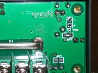
If you remove the 4 screws and the rear panel, you will find a pair of holes marked 'Ext PWR' and a jumper marked 'JMP2'.
Remove the jumper JMP2 and connect external power to the pair of marked holes. You need about 10V minimum, up to the rating of the meter. I used a small 12v wall wart. With external power applied, you can measure any voltage on the main input terminals, like a single cell. The jumper is just a blob of solder and is easily removed with a hot soldering iron. If you decide to replace the jumper, I found it difficult unless I used a small piece of wire.
With wires attached to the external power terminals, you can feed them out through the existing hole in the rear panel. The Amp-hour readings will stay intact as long as the extrnal power stays on. It will reset to zero when powered off.
External Power Input.jpg
 

Attachments

  • Meter rear panel.jpg
    Meter rear panel.jpg
    49.5 KB · Views: 1,925
Back
Top