DIY 6FET Controller help

SjwNz said:
The TRACO POWER has a 12V regulated output, its driving the six 1watt DC-DC supplies
It's hard to tell from the picture, but is the TRACO POWER 12V 250mA output? If so, then keep in mind this is only 3W, and you use that to supply a lot of stuff. So make sure you do some current measurements of the different parts to make sure the current capability of the TRACO POWER is sufficient.
 
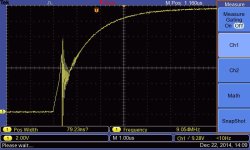
After looking at the gates of one of the HiSide fets which I was not to happy with as there was some weird stuff going on around the miller plateau area during turn on, I have a number of things to try but first I will lower the Gate turn on Resistor value current as its currently 40ohms.
but may have to add a Cap to the gate as the turn on time is already 250nS.
TEK0009.jpg

I also had to increase the phase current to around 140amps and increase Avg battery current to approx 75-80amps just to get
the amp meter I have connected to read 50amps, so not to sure whats going on there but will look into that more later.

I had a couple of desat shut downs that occurred while under hard acceleration when motor RPM was low, so started
to think it wasn't a shoot through event and maybe its just because the phase current is now closer to the desat trigger current as
I had to increase the phase current.

Anyway so far I have been terrorizing the neighbourhood riding around and got up to 55kms/h and although I only clocked up 14kms today, thats 10 times more than that crappy controller I posted at the start of this thread.
I still have a lot to do on this controller and still lots to learn but at least I am going in the right direction now.

Thanks everyone for your help.

P.S
In a month I maybe meeting the guy who Design this controller.

 
SjwNz said:
After looking at the gates of one of the HiSide fets which I was not to happy with as there was some weird stuff going on around the miller plateau area during turn on, (...)

Did you take the measurement with the ground clip and the probe directly on "top" of the FET?
 
eactly what Njay said. your picture looks what one would expect when using normal scope probes trying to measure a high-side fet. its extremely life threatening for your scope. only differential probes 600V rated should be used (or 1000V rated if you had 540Vdc bus)
 
Njay said:
SjwNz said:
After looking at the gates of one of the HiSide fets which I was not to happy with as there was some weird stuff going on around the miller plateau area during turn on, (...)

Did you take the measurement with the ground clip and the probe directly on "top" of the FET?

Yes Njay , later on that day after taking the picture of the gate on the HiSide, I decided to short out the Scope probe and connect it to the
Source on the HiSide, and there was the Spike/ringing that was showing up on the gate. Common Mode noise? Looks like I should buy a set of Differential probes.

HighHopes said:
eactly what Njay said. your picture looks what one would expect when using normal scope probes trying to measure a high-side fet. its extremely life threatening for your scope. only differential probes 600V rated should be used (or 1000V rated if you had 540Vdc bus)

Is it life threatening for your scope if I forgot that I had a GND lead on say CH1 on the HiSide MOSFETs source and then connected CH2s GND lead to Batt- which
would be a big short via the scope or a different reason?
 
Is it life threatening for your scope if I forgot that I had a GND lead on say CH1 on the HiSide MOSFETs source and then connected CH2s GND lead to Batt- which would be a big short via the scope or a different reason?

yes absolutely. there was a time when scopes would instantly explode (figuratively speaking) if you did that. now-a-days there is some built in protection against users misusing the equipment
 
So I have been having a small issue with Avg battery current, I have been trying to get 50amps , but can not quite get there (around 42amps) and the
Avg current has been set to 75amps. The phase current is currently set to 100amps, so am I correct in thinking I need to increase phase current
and then back off the avg current back to 50amps. Is there some rule for setting the max phase current?

Now that the bike is going I have a new problem, I need more power :) Looks like I need to work on a 12fet controller
 
SjwNz said:
So I have been having a small issue with Avg battery current, I have been trying to get 50amps , but can not quite get there (around 42amps) and the
Avg current has been set to 75amps. The phase current is currently set to 100amps, so am I correct in thinking I need to increase phase current
and then back off the avg current back to 50amps. Is there some rule for setting the max phase current?

Now that the bike is going I have a new problem, I need more power :) Looks like I need to work on a 12fet controller

You might not have the phase current set high enough to pull enough battery current. Just up the phase current leaving the battery current alone and see what happens. I went up in 25A steps. An additional 25 amps was more noticeable than I thought it would be and I eventually ran out of current sensor at 220A and couldn't go further (200A sensors). I've had some packaging issues on my 18 FET setup and want to do a little more bench time before I box it up. The current sensor I'm using don't have enough resolution +900A sensors. I want to go to the 300A sensor version which still reads a max of 900A but has a much improved resolution in the normal operating range.

BTW, the ring in your miller plateau is the same I see if I use my differential probe and have the 2nd channel ground hooked up as well. It can be difficult to get a clean picture without a differential probe setup and even now my old differential probes amplifier is fighting what I think is H field coupling from my driver. I'm dumping 600A pulses into a air coil so having a big EMF field isn't exactly surprising.
 
I increased phase current to 125amps and all good, just seeing battery current of 55 amps, so may start backing off the battery current setting.
Well , interesting last 4days . Thursday - Controller started cutting out on the way home from work and found my little sun shield to block IR from
the optical sensors was crap. So did a quick fix with duct tape and away it went until some wires got ripped up by the chain.
At this stage I thought my controller had died so pedaled back to work very sad, I fixed the wiring and away it went again.

So Friday night I made a better sun shield and gave the bike a quick test on Sat.
a3.jpg
a4.jpg


Sunday - decided to do a range test and rode around town , and by the end of the ride the controller was shutting down all the time.
So I had all these ideas about want mite be causing this, I was wondering if the RC filter on the Phase current sensors was to long (1k and 10nF 1TC=10uS),
Desat trigger leveled changed because it was hot that day, Maybe I overheated the motor and shorted out the windings.
Turn out that the stator had moved and stuffed up the timing.

Its been funny, as every time something like this happens I have been blaming the controller. But now the controller
has been the most reliable part on the bike.

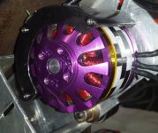
I have decided to get a bigger motor as the little motor I am using is getting a bit hot.
I will still use the 2kw controller for now but I am planing on making a 4 to 5kw ESC now.

Does anyone know if I am asking too much for a 12fet controller to do 200 to 250Amps Phase current using IRFP4468PBF mosfets (matched pairs).
Looking at using the RotorMax50cc motor from HobbyKing.

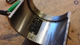
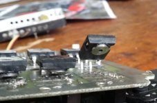
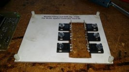
Some pics of how I mounted my mofets and screw them to the heatsink. (I have not seen this method before)
The small round metal things has a M3 thread inside it and I used a rubbery glue to hold it in place.
I then screwed the mosfet to the heatsink from the outside of the case. I did this so I didn't have to
have any access holes in the PCB which was a waste of space.
b1.jpg
View attachment 1
B5.jpg

I used your DC-Link guide HighHopes and have some polypropylene caps on the way. Straight after I was riding the bike I pulled
the cover off the controller and put my finger on the caps, lets just say I dont think they will last very long.
 
SjwNz said:
Can anyone recommended any other current sensors in the 300amp range.

I'm most likely going to be ordering these in the next day or so
http://www.digikey.com/product-search/en?pv276=8&FV=fff4001e%2Cfff801ed%2Cfffc018e%2C12040010&k=lem+current+sensor&mnonly=0&newproducts=0&ColumnSort=0&page=1&stock=1&quantity=0&ptm=0&fid=0&pageSize=25

I have the 600A version right now which are too much. The sensor will measure > 1000A but is only rated to 900A. I've tested this by making a single loop through the sensor and pulsing 600A through it. The resolution is just too small. The 300A sensor has a much wider output and is still rated for 900A peaks. Took a little math and digging into the datasheet for me understand how these sensors are rated, they are not straight forward like the Allegro sensors.

Another option is using 2 of the 200A Allegro sensors in parallel connected to a op amp. That gives a max reading of 400A.

If you are targeting 300A you'll need a minimum of 3 parallel MOSFETs, but don't expect them to do that current level for very long. putting 100A through the legs will not make them happy. For continuous use (60 mins) I think the TO-247 package is good for 25A , maybe 30 each. I'll know more when I test my design.

If you look at my Sevcon tear down, they have 10 MOSFETs and the continuous current is only 18A per MOSFET, but they can burst 60A each for 10 sec.
 
zombiess said:
SjwNz said:
Can anyone recommended any other current sensors in the 300amp range.

I'm most likely going to be ordering these in the next day or so
http://www.digikey.com/product-search/en?pv276=8&FV=fff4001e%2Cfff801ed%2Cfffc018e%2C12040010&k=lem+current+sensor&mnonly=0&newproducts=0&ColumnSort=0&page=1&stock=1&quantity=0&ptm=0&fid=0&pageSize=25

I have the 600A version right now which are too much. The sensor will measure > 1000A but is only rated to 900A. I've tested this by making a single loop through the sensor and pulsing 600A through it. The resolution is just too small. The 300A sensor has a much wider output and is still rated for 900A peaks. Took a little math and digging into the datasheet for me understand how these sensors are rated, they are not straight forward like the Allegro sensors.

Another option is using 2 of the 200A Allegro sensors in parallel connected to a op amp. That gives a max reading of 400A.

If you are targeting 300A you'll need a minimum of 3 parallel MOSFETs, but don't expect them to do that current level for very long. putting 100A through the legs will not make them happy. For continuous use (60 mins) I think the TO-247 package is good for 25A , maybe 30 each. I'll know more when I test my design.

If you look at my Sevcon tear down, they have 10 MOSFETs and the continuous current is only 18A per MOSFET, but they can burst 60A each for 10 sec.

You can also get the 900A sensor and loop the wire through 3 times to make it a 300A sensor.... This way you have a configurable sensor with a max rating of 900/N, with N the number of winding you use. I would not mess around with using two 200A sensors in parallel, and if you do you definitely don't need an opamp.
 
If you are targeting 300A you'll need a minimum of 3 parallel MOSFETs, but don't expect them to do that current level for very long. putting 100A through the legs will not make them happy. For continuous use (60 mins) I think the TO-247 package is good for 25A , maybe 30 each. I'll know more when I test my design.

Was looking at 200 to 230amps phase and 100amps Avg Batt , not sure if I can get that with two TO-247s . I am currently at 125amps phase
with one fet and when I get this bigger motor I will try increasing phase current up to 150amps or maybe more to see what the limit is.
I will need to fit a temperature sensor to one of the fets when doing this test. So if I get to 150 or more with 1 fet, when I make a
12fet controller around the 230amp phase limit, thats 115amps per fet, we will see what happens.
This power rating I am trying to get to will only be for short time, maybe 1 to 2mins but there will be a temperature sensor fitted .
I just hope I dont have to buy to many 4468 fets to get matched pairs.

Thanks guys for the options on the sensors, Futterama I had been thinking of doing the shunt across the Allegro sensors some time ago but was not sure how well it would work but will look into it again as its the cheapest option, well cheapest in parts but not so much in time :)
Lebowski, I forgot about more turns around the sensor, I had to do that on a small current transformer some time ago.

I just relished today I have been running my controller with a large amount of deadtime around 6uS with a 15KHz PWM freq.
Will this generate a lot of ringing/spikes and load up the freewheeling diodes and generate more heat?
 
SjwNz said:
I used your DC-Link guide HighHopes and have some polypropylene caps on the way. Straight after I was riding the bike I pulled
the cover off the controller and put my finger on the caps, lets just say I dont think they will last very long.

How much capacitance did you calculate and how many KW do you think the controller will produce continuously? HighHopes has stated that the document is just a basic guideline to get a very rough estimate.
 
Lebowski said:
You can also get the 900A sensor and loop the wire through 3 times to make it a 300A sensor.... This way you have a configurable sensor with a max rating of 900/N, with N the number of winding you use. I would not mess around with using two 200A sensors in parallel, and if you do you definitely don't need an opamp.

I know I can loop the wire through, but I don't have the space for looping them and fitting them in the case. The LEM HAAS sensors are rated in RMS current vs peak current which is kinda funky.

I need to crunch some numbers, but I think I'm going to switch to the HASS 200-S which go to 600A.

Lebowski, can you tell us how many usable bits of resolution do you get from a current sensor?
 
can you not just run 2 power wires, one through the sensor, one outside of it

it doesn't really matter how accurate it is, as long as it's consistent ?

couple of % either way makes no difference?
 
I used your DC-Link guide HighHopes and have some polypropylene caps on the way. Straight after I was riding the bike I pulled
the cover off the controller and put my finger on the caps, lets just say I dont think they will last very long.
just so i understand, you used my method and then found that the caps are getting hot? or you had some other caps found they got hot so changed to use my method (i.e. with polypropelene)? if my method, please post your math. cause its generic method but supposed to lead to slight conservative results, shouldn't be getting hot.

thanks for the link on extending allegro sensor, that's really neat. wonder how well it works over entire range. i'll read. personally, i'd like to spend my time advancing the PCB Regowski Coil method instead, but that's a discussion for another day.
 
zombiess said:
SjwNz said:
I used your DC-Link guide HighHopes and have some polypropylene caps on the way. Straight after I was riding the bike I pulled
the cover off the controller and put my finger on the caps, lets just say I dont think they will last very long.

How much capacitance did you calculate and how many KW do you think the controller will produce continuously? HighHopes has stated that the document is just a basic guideline to get a very rough estimate.

Looking at 2Kw continues but my motor will not handle that for long so until I get this bigger motor or build a test stand it maybe sometime before I
can run it at power for any lenght of time. Yep, I understand HHs DC-Link cap doc is a guideline.

HighHopes said:
just so i understand, you used my method and then found that the caps are getting hot? or you had some other caps found they got hot so changed to use my method (i.e. with polypropelene)? if my method, please post your math. cause its generic method but supposed to lead to slight conservative results, shouldn't be getting hot..

The hot caps were some I got 6 months ago which I am still using at the moment and the values were not based on your DC-Link guide.
I had come up with values using your guide to replace the crappy caps I am using, but I based it on my motor inductance of 66uH
which was measured with the rotor removed as I saw my friends YouTube video about testing the motor windings and the rotor
was removed so the magnets did not affect the reading.
Maybe a silly question but should I be measuring the motors inductance with the motor assembled in which case I end up with 33uH.

Had a good day , I rewired the motor with 1.3mm wire, fixed the stator from moving on the bearing housing and reduced the deadtime to
2% instead of the stupid 8% I had. Big difference in power now, It will easily get to 2kw :)
 
Back
Top