DIY 6FET Controller help

deadtime has a real influence on torque production. 8% is stupid, so ya you will see a change when you go to 2%. just make sure 2% is OK for you as it is fairly low because it's catastrophic failure potential if not good value. i put in detail somewhere how to calculate a worse case value by analysis. my goal is to keep deadtime to 5% or less.

i would measure with motor assembled. the inductance will change based on the position of the rotor so you can see a range of values
 
SjwNz, I was looking over your thread again because I just started fiddling with the DESAT capable gate drivers and I have a few questions for you:

1. Why do you use a 1k resistor in the DESAT path when the ACPL-333J recommends a 100Ω resistor?

2. Why don't you have the R(pull-down) resistor directly on the Vout pin on the ACPL-333J as recommended in the datasheet (page 21) to sink the static 650µA current?

3. Why don't you have the schottky and zener connected to the DESAT pin to prevent false triggering as explained in the Avego AN-5324 (chapter 4, page 4)?

4. How did you measure the DESAT threshold of the gate drivers? I saw you used a SOIC socket, but how was the gate driver IC connected and how did you manage to find the DESAT threshold?

5. Which brand/partnumber DESAT zener diode did you use?
 
1. Why do you use a 1k resistor in the DESAT path when the ACPL-333J recommends a 100Ω resistor?
I was so sure I saw this in the datasheets, something about 100 to 1K but I was wrong, so will be using 100Ω in future controllers.

2. Why don't you have the R(pull-down) resistor directly on the Vout pin on the ACPL-333J as recommended in the datasheet (page 21) to sink the static 650µA current?
I was to busy looking at other peoples placement of this resistor and did not notice it in the datasheet. So another change to make.

3. Why don't you have the schottky and zener connected to the DESAT pin to prevent false triggering as explained in the Avego AN-5324 (chapter 4, page 4)?
I missed that, thanks.

4. How did you measure the DESAT threshold of the gate drivers? I saw you used a SOIC socket, but how was the gate driver IC connected and how did you manage to find the DESAT threshold?
I had a scope across the Desat cap and did not have the fet connected, so every time I sent a pulse to drive the chip i got a desat trigger. I looked at the
peak voltage across the desat cap, as when the Desat kicked in and the gate turned off the Desat pin is shorted to the 333J gnd to discharge the cap.
It was something like that, after I tested them all I stopped worrying about the threshold difference between the chips and sort of forgot exactly what I did.

5. Which brand/partnumber DESAT zener diode did you use?
I dont know :oops: I just got them from work, I remember I tested it's voltage with a 250uA current flowing through it but I need to
get them in SMD for the next controller.
 
SjwNz said:
1. Why do you use a 1k resistor in the DESAT path when the ACPL-333J recommends a 100Ω resistor?
I was so sure I saw this in the datasheets, something about 100 to 1K but I was wrong, so will be using 100Ω in future controllers.
The datasheet for the similar device from Fairchild Semiconductor, the FOD8332, mentions 100Ω to 1kΩ resistor, maybe you have been looking at that? It also says that the resistor will not alter the DESAT threshold, that's not true since the 100Ω resistor will have a voltage drop of 25mV with 250µA through it. Not much, but with 1kΩ the voltage drop will be 250mV or 0.25V which does have a noticeable effect on the threshold.
The resistor is there to limit the current draw out of the IC when there is a negative voltage spike on the DESAT pin from the IGBT (and MOSFET as well I guess) freewheeling diode. I don't know how big this voltage spike can get or how much current the IC can handle out of the DESAT pin so I would just go with the recommended value from the datasheet when nothing else is mentioned.

SjwNz said:
2. Why don't you have the R(pull-down) resistor directly on the Vout pin on the ACPL-333J as recommended in the datasheet (page 21) to sink the static 650µA current?
I was to busy looking at other peoples placement of this resistor and did not notice it in the datasheet. So another change to make.
The datasheet does not mention anything about why the voltage must not rise to VCC2, other than the pulldown is recommended. They also talk about "3 VBE" which I guess is a voltage, but I can't find any numbers for VBE, so I submitted a support request to Avego. Maybe VBE = 0.7V but I wanted to be sure since the pulldown resistor value is dependent on it.
Also if "3 VBE" is 2.1V, the gate of the MOSFET would get VCC2-2.1V and not VCC2. So with VCC2 = 15V, the actual gate drive voltage would be 12.9V. If this is really the case, why is it not stated anywhere in the datasheet? I will test this, I'm too curious :lol:

SjwNz said:
3. Why don't you have the schottky and zener connected to the DESAT pin to prevent false triggering as explained in the Avego AN-5324 (chapter 4, page 4)?
I missed that, thanks.
The schottky diode will prevent the DESAT pin to go to a negative voltage, but then we are back at the 100Ω vs. 1kΩ resistor, since the schottky will have to be able to conduct the current, and so will the DESAT blocking diode and voltage drop zener diode.
The protection zener at the DESAT pin, should prevent the DESAT voltage to get above 10V, so a 8-9V zener is probably what is needed. This zener should also be able to handle the current that the 100Ω-1kΩ resistor is limiting, right?
These 2 protection diodes should probably also be low leakage type since their leakage current will come from the 250µA current source from the DESAT pin. Also the schottky diode forward voltage should be as low as possible since the DESAT pin absolute maximum rating voltage is VE to VE+10V and any forward voltage would actually violate this limit, but 500mV (as the MBR0540 shown is rated) would probably not be high enough to forward bias the device's substrate, so 500mV or less forward voltage of the schottky will be good.

SjwNz said:
4. How did you measure the DESAT threshold of the gate drivers? I saw you used a SOIC socket, but how was the gate driver IC connected and how did you manage to find the DESAT threshold?
I had a scope across the Desat cap and did not have the fet connected, so every time I sent a pulse to drive the chip i got a desat trigger. I looked at the
peak voltage across the desat cap, as when the Desat kicked in and the gate turned off the Desat pin is shorted to the 333J gnd to discharge the cap.
Very smart :)

SjwNz said:
5. Which brand/partnumber DESAT zener diode did you use?
I dont know :oops: I just got them from work, I remember I tested it's voltage with a 250uA current flowing through it but I need to
get them in SMD for the next controller.
Take a look at these:
http://www.centralsemi.com/PDFs/products/CMOZ2L4_SERIES.PDF

Their zener voltage is rated at 250µA, and they have a very large selection of zener voltages, I guess you could series connect 2 or more zeners and with this selection, you could tweak the DESAT threshold to within something like 0.1V :D
 
Futterama said:
These 2 protection diodes should probably also be low leakage type since their leakage current will come from the 250µA current source from the DESAT pin.
What I call leakage current, is actually called reverse current, sometimes reverse leakage current, sorry for the use of slightly wrong terms.

I just did a quick test. The reverse current of the protection schottky does impact the 250µA from the DESAT pin. Luckily the reverse current is usually very low at the voltages present on the DESAT pin. Example is the MBR0540, which I have a few samples of here with me. The rated reverse voltage is 40V. According to the Electrical Characteristics, the reverse current at 20V/25°C is 10µA, at 40V/25°C it's 20µA. At 100°C it's much higher, 5mA@20V and 13mA@40V :shock:
The graph in the datasheet shows a lot lower reverse current at e.g. 10V/25°C it's 0.5µA. However, the graph does not agree with the Electrical Characteristics, WTF?
Anyway, according to the graph, keep the temperature below 75°C or the reverse current rises to above the 250µA current source :roll:

My test showed 1-2µA less DESAT current with the MBR0540 added between the DESAT pin and VE with a DESAT voltage at about 5.6V.
The zeners from Central Semi (see linked datasheet in my previous post) also have low reverse leakage current according to the datasheet. I would probably pick the CMOZ9L1 (9.1V version) which has a maximum reverse current of 1µA at 6V so this wouldn't impact the 250µA current source much, and the 5% zener accuracy is within "maximum DESAT voltage" and 10V.

Only problem is to find a distributor of the zeners from Central Semi that carries a wide selection of zener voltages. I requested some samples directly from them, lets see what they respond.
 
Futterama said:
SjwNz said:
4. How did you measure the DESAT threshold of the gate drivers? I saw you used a SOIC socket, but how was the gate driver IC connected and how did you manage to find the DESAT threshold?
I had a scope across the Desat cap and did not have the fet connected, so every time I sent a pulse to drive the chip i got a desat trigger. I looked at the
peak voltage across the desat cap, as when the Desat kicked in and the gate turned off the Desat pin is shorted to the 333J gnd to discharge the cap.
Very smart :)
I just found another way, maybe even more accurate and simple. Maximum DESAT threshold is 7.5V. Resistor value needed to get a 7.5V voltage drop at 250µA: 7.5V/250µA = 30kΩ.
So connect a 50kΩ multiturn pot from DESAT pin to VE and start with a low value setting. Measure DESAT voltage with a multimeter (beware this might consume some of the 250µA current). Increase resistance until DESAT triggers and DESAT voltage goes to 0. Take note of the voltage at which the DESAT triggered.
 
SjwNz said:
Futterama
I tested the Desat threshold voltage levels last night and found that the 9 chips I tested were very very close which was good.
but not so good was the threshold dropped by 0.2V when I heated the driver up to approx 50°C . this will lower the desat trigger current
so I would have to set a much higher Desat trigger current when the controller is cold to make sure the desat current does not get to low and triggers all the time
when the controller heats up.
I just tried heating my FOD8332 test device, the actual DESAT threshold stayed within 0.05V but the DESAT output current dropped to around 180µA with a hot chip (not able to hold my finger for long on it).
The effect of this, at least on my board, is a slightly higher DESAT threshold which means higher MOSFET current before DESAT tripping.

I tried heating the zener diode only (took it off the PCB) and the zener voltage will fall slightly with higher temperatures, someting like 50mV in my case. But not enough to counteract the drop in DESAT output current.

At my first try with heat, the DESAT output current would drop rapidly with heating, and I found that it was the DESAT protection schottky (the one from DESAT pin to VE, MBR0540) that increased in reverse leakage current, all the way to the point where the reverse leakage current was higher than the DESAT output current, so the schottky basically leaked all of the 250µA from the DESAT pin and completely disabled the DESAT circuit :(

So pick your DESAT pin protection diodes, both schottky and zener, with great care and test at elevated temperatures. I'm adding several temperature sensors in my controller, perhaps I should place some near the protection schottky diodes just to make sure they don't get so hot they disable the DESAT circuit. I might even need to consider forced air cooling of the PCBs to keep a more stable temperature inside the controller case.
Looking at datasheet graphs of the schottky diodes regarding reverse current vs. reverse voltage and temperature, the ambient (controller case/PCB ect.) temperature should not exceed 75-85°C or the reverse current will be excessive.
 
DESAT is designed to protect against shoot through, not overcurrent. In a real DESAT event the voltage across the FET will be heading for something like VBatt/2, so the signal is not subtle at all. Repurposing it for an overcurrent detector is changing the design purpose of the feature, and thus it becomes difficult.

Overcurrent at these lower levels would probably be better handled by temperatures of the FETs and not by trying to make the DESAT circuit do the job.
 
Alan B said:
DESAT is designed to protect against shoot through, not overcurrent.
Well, shoot through is a severe overcurrent event through the MOSFETs, isn't it? I'm not sure what your point is here, you don't think it is good design to figure these things out? Before I started digging, I had no idea that elevated temperatures on the gate driver board could completely disable DESAT detection as it is the case when the protection schottky leaks all the DESAT current. And by disabled, I mean it won't trip at all.

HighHopes said:
the desat circuit is used to protect the drive from shoot-through event, when both adjacent mosfets are ON at the same time thus short-circuit the DC link capacitor to ground. the phase out current sensor would never see this current because it does not flow in that direction.

desat circuit should trip at 200% FLA. as junction temperature ggoes up, the threshold drops, but if it started at 200% you got some room to drop.
I am not familiar with the term "FLA", but my guess is the DESAT should trip at twice the rated peak current of the controller, am I right or wrong?
And junction temperature is the MOSFET temperature, if the gate driver board temperature rises equally, this will counteract each other: MOSFET temperature rise decreases threshold (due to the rise in RDSon and this will give a bigger voltage drop across D-S), gate driver board temperature rise, increases the threshold due to lower DESAT current and higher zener voltages.
 
Alan B said:
DESAT is designed to protect against shoot through, not overcurrent. In a real DESAT event the voltage across the FET will be heading for something like VBatt/2, so the signal is not subtle at all. Repurposing it for an overcurrent detector is changing the design purpose of the feature, and thus it becomes difficult.

Overcurrent at these lower levels would probably be better handled by temperatures of the FETs and not by trying to make the DESAT circuit do the job.
Sorry, I have to comment on this again.

I am not trying to repurpose the DESAT detection for an overcurrent detector (what makes you think I do?), I'm just trying to understand how and why to pick the parts for it so I can get the most reliable system possible. Also, I would like a predictable system, even with regards to the DESAT trigger current through the MOSFETs. It might not REALLY matter if it triggers at 100A or 400A, but if I feel like I want it to trigger at 250A, I will try to make it do that because that's what makes me happy.
The journey to get there is also very educational for me, and a big part of making my own controller, is to know HOW it works and why, so I really like this kind of discovery work :wink:
 
SjwNz, I noticed you used a 33pF blanking capacitor on the DESAT pin. From the ACPL-333J datasheet:
The capacitance value can be scaled slightly to adjust the blanking time, though a value smaller than 100 pF is not recommended.
...
The recommended 100pF capacitor should provide adequate blanking as well as fault response times for most applications.
 
Futterama said:
I am not familiar with the term "FLA", but my guess is the DESAT should trip at twice the rated peak current of the controller, am I right or wrong?
And junction temperature is the MOSFET temperature, if the gate driver board temperature rises equally, this will counteract each other: MOSFET temperature rise decreases threshold (due to the rise in RDSon and this will give a bigger voltage drop across D-S), gate driver board temperature rise, increases the threshold due to lower DESAT current and higher zener voltages.

FLA = Full Load Ampers

Junction temp != MOSFET temp... depending on what you mean. There are several temperatures involved with a MOSFET as I'm sure you already know, so it's best to specify exactly what you mean. I'm guessing you meant the junction w.r.t. the desat function.

Did you happen to record the actual temperature when the schottky diode became an issue? Best practice is to keep everything below 80c to extend the life of the components.

It's great when you can heat everything up and measure stuff at different temperatures, I would like to build a small environmental test chamber myself. Just one more thing on the long list of "nice to have" stuff.
 
With junction, I meant it was the MOSFET that was referred to, not the junction in the gate driver chip or any of the diodes.

I did not record any temperatures yet, I only pointed a heatgun to the PCB. I have already considered how to make a box for heating stuff, I'm thinking a big aluminium plate on top of my hotplate/reversed clothes iron, the block of aluminium will help keep a steady temp and then a wooden box around it with a clear polycarbonate lid and a hole for the wires. I would probably have to find another temp sensor than my cheap multimeters temp probe or my Fluke's thermocouple since I would need the multimeters for other measurements. Hmm, I have a cooking thermometer with a sensor on a wire, it should work ok to get +/- a few degrees.
 
This is what I use to log temperatures on controllers. It has 4 channels and you can download the data over USB.

UEI DT304
http://www.amazon.com/DT304-Input-Digital-Logging-Thermometer/dp/B0039LAVEM/ref=sr_1_22?s=industrial&ie=UTF8&qid=1422910217&sr=1-22&keywords=4+channel+thermometer

If you are inclined, you could also make your own logger using a micro controller. There are other options out there to purchase. Ebay is probably a good resource.

I prefer K type thermocouples myself because they have a wide temperature range and they can be soldered to spots you want to measure.
 
ADT7301 + SPI capable PIC with UART + MAX232A + serial-to-USB converter + terminal program = my kind of logging :mrgreen:

EDIT: Add a few more ADT7301 devices and a 16x2 backlit LCD display to that and I got myself a little project :D

Don't really need logging, just get the temperature to selected value and then test the circuit. But I have to wait until I get a new 440mA fuse for the Fluke, I fried the fuse earlier today :roll: and it's my only µA capable multimeter. I fried the 11A fuse a while back, man those things are expensive, €27 just for one of each type fuse :shock:
Hopefully I have a new 440mA fuse tomorrow, the 11A was not in stock.
 
I just received reply from Avago regarding the VBE voltage:

Dear Mr. Jakobsen,

You are correct that we don't actually define the value of Vbe. Our apologies for that. In general this is standard for silicon transistors at a value of 0.7V.

Please let us know if you have any further questions on this topic.

On another note, if you are working on a new design with ACPL-333J, you may also be interested to know that there is a next generation device already available with rail to rail output. This is the ACPL-336J/337J family in case you are interested to consider these. http://www.avagotech.com/pages/en/optocouplers_plastic/plastic_integrated_gate_drive_optocoupler/acpl-336j-000e/

Kind Regards,
Olaf Wagner
New generation devices? :D

The ACPL-337J is a 4A output device :p compared to the ACPL-333J which is 2.5A 8)
The ACPL-336J is also a 2.5A device but has stronger Miller Clamp and probably other stuff too that's better than the ACPL-333J.

EDIT: The new devices include an input LED driver, seperate UVLO fault output, rail-to-rail output and higher DESAT current of 1mA which makes it easier to find a suitable zener diode. Really cool :D

MORE EDIT: Digikey don't have them without high minimum quantity, but farnell has them, and the price is lower than for the ACPL-333J. The ACPL-333J price has gone up since last time I checked, but the ACPL-337J is 30% cheaper than the price I recorded for the ACPL-333J long time ago, and now it's 40% cheaper due to the price increase of the ACPL-333J. So I'm happy I didn't get around to order the ACPL-333J yet, I'm getting the ACPL-337J instead :D
 
Futterama said:
And sorry to SjwNz for kinda hijacking your thread :roll:

No worries :)

Looks like this new 337J will be going into my 12fet controller.

My RotorMax50cc motor turned up and I have been carrying it around with me for the last 2days showing it to people.
I love this motor and this new 337J driver chip.
Farnell (Element 14) already have the 337J in stock.
 
i'm very glad nobody even entertains the idea of a bootstrap cheapy anymore. its not even on the radar.
337J looks like another good one. interesting that they are using 1kOhm in desat circuit. i always liked much lower values but then i always had decent switching performance due to very high quality components & custom fabricated eveythings. for DIY world, might be that a 1kOhm is better.. but try not to go higher than that or other things will suffer.
 
The belt from the motor to first gear broke about 3weeks ago, Ok I was doing burn outs in the shed.
Anyway, after this happen I pulled out the old motor and made some new mounts for the
new motor and had it running 3days ago. I even manged to make my own 16tooth pulley with out
needing the mill as I don't have a dividing head.
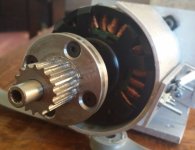
gear.jpg


I am not to happy with my crappy mounting of the motor and gears
and plan on rebuilding this to try and get away from the DIY look.
Currently learning to use solid works so will draw up my new design on that.
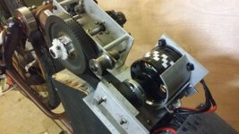
gearbox.jpg

This motor has an inductance of 10uH and so far the controller is doing well.
But I really need to change the DC-Link caps now as they will
be extra stressed now with only 10uH.

I did have a 40uF PP cap waiting to be fitted but I manged to mess up
and it will not fit, so now have five 470uF caps with a ripple current rating of 2.4amps
at 100KHz @ 105°C. This was all based for the 30uH motor but this 10uH motor has messed things
up a little bit.
Using 10uH motor and 15KHz PWM with a min battery voltage of 38volts gives me a ripple current of
44amps. :shock:

Ripple Current: Using HighHopes Guide.
delta_I = d*(1-d)*Vbus/(f*L)
delta_I = 0.5*(1-0.5)*38V/(15kHz*10uH)
delta_I = 63App or 44Arms

So, I am a long way from having enough caps but I am still going ahead
with the 5 x 470uFcaps and we will see how long it takes for the caps to open up like the
eggs in the Aliens movies.
I may have to increase PWM freq to 20KHz to help reduce the ripple current.

So far I have only done two short rides with the new motor and due to the lower motor inductance
I am now pulling up to 70amps batt current (2500watts).
Looks like I forgot to back-off the Avg current setting which was left at 75amps
as the old motor could never draw that much current.

In a week or so I will try increasing the phase to 150amps, and will get some scope pics
of a lowside gate and a phase output. I may have to increase desat to 300amps as well
if I increase the phase current.

I was going to build a 12fet controller but this is a waste of time at the moment as I don't
think my bike components ( chain and the timing belt ) will handle 5kws,
so I have decided to make the 6fet controller again but smaller, use a 40 pin PIC
and layout the digital board so it is pin compatible with Lebowski's Controller chip.

The aim is to try and make this bike not look DIY as much as possible which is funny, as
5 months ago the aim was to make a controller that lasted longer than 5mins.
I don't think this project will ever end :D
 
I wanna know how you made that pulley, it looks real pro made :D

Even I was impressed with my gear :) . I just made a drawing using my PCB program to layout the holes and printer that to paper.
Then double sided taped it to the round metal rod and using the drawing punched the centers for the 16 holes.
I then drilled the holes for the teeth, put the rod in the lathe and turned down the rod until I reached the 16 holes.
Then finished off with a Dremel to round off the teeth.

I increased the phase current to 150amps today, but Desat was triggered every time I opened the throttle quickly,
I am picking its due to the low motor inductance of 10uH and the current is ramping up faster than the current sensors
can respond too. The Desat is still only set to 240amps so will increase it to 300amps and will test again.
 
i wish i could do machine work like that. good job!

I increased the phase current to 150amps today, but Desat was triggered every time I opened the throttle quickly,
sounds like you have very high ripple current: V = L*di/dt --> di = V*dt/L

if you want smaller peak current (so you don't stress your mosfets) you need smaller dt which is same as saying faster switching frequency. with 10uH i would target 40kHz design. i don't know if your gate driver and system can handle that but is worth a try to get there.
 
Lots of good info the last while in this thread.
 
SjwNz said:
I wanna know how you made that pulley, it looks real pro made :D

Even I was impressed with my gear :) . I just made a drawing using my PCB program to layout the holes and printer that to paper.
Then double sided taped it to the round metal rod and using the drawing punched the centers for the 16 holes.
I then drilled the holes for the teeth, put the rod in the lathe and turned down the rod until I reached the 16 holes.
Then finished off with a Dremel to round off the teeth.

I increased the phase current to 150amps today, but Desat was triggered every time I opened the throttle quickly,
I am picking its due to the low motor inductance of 10uH and the current is ramping up faster than the current sensors
can respond too. The Desat is still only set to 240amps so will increase it to 300amps and will test again.
Wow that's dedication. That's my kind of style.
 
Back
Top