
You are using an out of date browser. It may not display this or other websites correctly.
You should upgrade or use an alternative browser.
You should upgrade or use an alternative browser.
E+ powered by A123 20 Ah pack UPDATE
- Thread starter miro13car
- Start date
miro13car
100 kW
From the pictures I can tell your Eplus didn't run many miles,right?
Did you consider selling it?
I wil grab any Eplus with below 1000 millage in good shape
Did you consider selling it?
I wil grab any Eplus with below 1000 millage in good shape
BVH
1 kW
- Joined
- Mar 26, 2009
- Messages
- 411
I'd guess it has between 1000 and 1500 miles on it. (I went thru a few controllers when new) Back in my motorcycle days, I would not ride the MC unless it was spotless and the same goes for the E+ (except right now it has lots of dust on it from sitting and I actually rode it) The bike has never seen water of any kind. I use only polish to clean it. It's pretty much in 98.5% Mint condition. I love riding it and when I don't for a while, when I get back on, It's like getting a new one all over again. I don't want to sell it.
miro13car
100 kW
Of course you would not sell it in your right mind
I was just kind of teasing
If you rode other electric bikes you know the difference
I was just kind of teasing
If you rode other electric bikes you know the difference
BVH
1 kW
- Joined
- Mar 26, 2009
- Messages
- 411
I have and I agree with you 100%. My first was a Commencal with Black Lightening (Gen3, I think) motor and 30 Amps of 14S Lipo pacs. It was quite the rocket but being a mtn bike, It gave me wrist and back aches from the riding position. I love my bolt-upright riding position now! I've also changed out 5 of the rear cluster cogs to give me a 32 tooth hill climber while maintaining the 11 tooth cog for speed. And I swapped out the standard derailleur with a Shimano XTR.
BVH
1 kW
- Joined
- Mar 26, 2009
- Messages
- 411
I finally read the entire thread and noticed a few references to the two EMS batteries - the front Nimh and the rear Lipo, running in parallel. (if I interpreted the posts correctly?) I do not believe this is the case and also I was told this by my selling dealer who said he had got his info from Rick at EMS, that the controller isolates the two batteries at all times. If they were in parallel, there would be no reason to change from A to B on the controller and running on either battery would also run the other one down, which does not happen. (If I mis-read the posts, then disregard the above) So assuming they are not running parallel, why does the battery cable (large) connector on the front hub battery need to be disconnected when running on a Non-EMS rear connected battery?
I forgot how much capacity the OEM Lipos have. I pedal full-time but also have at least 100 Watts throttled in 80% of the time and an average is probably closer to 300 Watts. Today on somewhat hilly terrain, I got 27.4 miles out of the Lipo.
EDIT ADDED: Just did a full charge on both packs - the Lipo was done outside on a concrete pad. With all cables plugged in, controller functions as it should. With power off, I unplugged the Nimh hub battery cable only, left the comm cable connected. I powered up the controller and once the display settled, I switched to the rear "B" pack. The display indicated all was fine but there was no power to the motor and the display shuts off in a few seconds. So on my E+, I cannot ride on the "B" battery alone. I tired this 4 times with the same results. Next, I've never been able to measure Voltage out of the "B" battery. Then it dawned on me that I probably have to have the controller on and the "B" battery selected. This is precisely correct. The control system will not allow the logic in the "B" battery to provide any power on the output cables until the "B" battery is selected. At no other time, is there power on the "B" battery output cables. This is further evidence that the batteries are not paralleled. BTW, after 45 minutes rest, my Lipo is at 42.1 off the charger, or 4.21V per cell. Seems it's a touch too high. I'd rather see 4.19 or 4.18 after a rest. That means it was probably 4.22 or 4.23 at some point just after termination. Maybe a contributing factor to the "problems" that caused the recall?
ebikesrfun
100 µW
- Joined
- May 23, 2012
- Messages
- 8
Here's some info to help clarify the third party battery situation on an E+. The power wiring that connects to the front hub battery is in parallel with the wiring that allows connection to the rear battery.
If you were to leave the NiMh battery plugged in and then connected an aftermarket battery, they would be wired in parallel. It seems that the rear com connector allows the controller to know that there is a "B" battery installed and then proceeds to isolate each one. Since aftermarket batteries do not have this com connector, the controlled still thinks only the NiMh is plugged in.
When using a third party battery, leave the front com connector plugged in and leave the hub battery power connector unplugged. Plug in your third party battery to the rear power connector and then turn on the system. This works well aside from the 10 minute sleep timer which turns the system off at exactly 10 minutes on the dot.
I've been trying to figure out how to stop this from happening. Lately, I've been experimenting by attaching lights and other DC-DC devices to the NiMh to see if I can trick the system into not going to sleep.
Has anyone figured out a solution to this sleep timer situation?
ambroseliao
100 kW
Why do you need to unplug the NiMH front hub? Can't you keep them in parallel?
Miro13car, how are you able to stop the 10 minute timer from shutting the bike down?
Miro13car, how are you able to stop the 10 minute timer from shutting the bike down?
dnmun
1 PW
i don't think they are in parallel. it seems like the controller choses on or the other. you haven't explained how the controller works.
i explained early on that you should be able to go directly to the wiring of the nimh pack and attach the 48V lifepo4 pack in parallel through a 20-30V diode. that will give you full use of the nimh and the lifepo4 pack. leave it attached and charge while it is set up that way. nobody ever answered about the 57V limit, why not?
i explained early on that you should be able to go directly to the wiring of the nimh pack and attach the 48V lifepo4 pack in parallel through a 20-30V diode. that will give you full use of the nimh and the lifepo4 pack. leave it attached and charge while it is set up that way. nobody ever answered about the 57V limit, why not?
ambroseliao
100 kW
dnmun said:...nobody ever answered about the 57V limit, why not?
No one has bothered to test the EMS up to that voltage, however, I doubt that it would be that high for a 36V system. Logically, it should be around 45V since NiMH can reach that voltage during charging. I am eager to find out about my Tidalforce motor/controller to see what the HVC limit is. The higher the better since the TF is a closed system very much like the EMS system.
dnmun
1 PW
well why do they continue talking about connecting a lifepo4 pack in parallel? it is not in parallel. it is a separate pack to the controller. they should actually really connect the lifepo4 pack in parallel using the nimh connection and forget about the other connector. but it needs a 20V diode on top of the nimh.
i can give you a part number if you need to find the diode.
i can give you a part number if you need to find the diode.
ambroseliao
100 kW
That would be very helpful!
dnmun
1 PW
mouser part# (these are ON semiconductor axial diodes.)
863-1N5817G 20V, 25A, .45V forward bias $.28
863-1N5818G 30V, 25A, .55V forward bias $.26
863-1N5817G 20V, 25A, .45V forward bias $.28
863-1N5818G 30V, 25A, .55V forward bias $.26
ambroseliao
100 kW
Thanks dnmun!
ebikesrfun
100 µW
- Joined
- May 23, 2012
- Messages
- 8
dnmun said:well why do they continue talking about connecting a lifepo4 pack in parallel? it is not in parallel. it is a separate pack to the controller. they should actually really connect the lifepo4 pack in parallel using the nimh connection and forget about the other connector. but it needs a 20V diode on top of the nimh.
i can give you a part number if you need to find the diode.
When you look at the wiring up close, the front and rear battery connectors are in parallel. There is only one set of positive and negative wires entering the hub motor/controller.
My intent with only using the A123 battery is to avoid using the NiMh hub battery due to its limited number of charge cycles and high cost for cell replacement. Sending it back to Rick for repair would be both costly and frustrating as he takes a long time to do things from my experience.
BVH
1 kW
- Joined
- Mar 26, 2009
- Messages
- 411
Unfortunately, I'm not going to add a solution here now but will add some pieces to the puzzle.
With all 6 connectors disconnected - 2 at Batt A, 2 at Batt B and 2 on the display, there is momentary continuity between the harness connector for Batt A + and harness connector for Batt B +, but it lasts for only a fraction of a second and then some logic somewhere in the wiring harness cuts the connection because this happens with the display and hub controller disconnected from the system. Give it 10 seconds to "reset" and you can do it all over again. Less than 5 seconds, there is no continuity.
There are 3 motor phase wires entering the bottom of the frame down tube and then run up the tube and there are 3 additional cables from the Battery B entering the frame down tube and also heading up the tube. There is no other exit point in that tube other than at the top where only 4 cables exit. So is there some type of interconnect/splice and maybe logic located in the frame down tube? There are only 3 phase wires going to the motor so probably no logic located in there. How do the 3 Phase wires going to the motor ultimately get their actual power from the controller? Where is that interconnect? I would expect to see 3 large cables in the Batt "A" connector? All of the wires going to the controller are so tiny that they could not handle the load. Is it all done in the front battery hub and if so, there are not enough wires coming out of the front hub to account power (2) and 3 phase wires. Sure be nice to see a schematic!
miro13car
100 kW
Before reading, please consider that I might be wrong in some of my concepts and theories. I am only human, trained but human so I make mistakes
if you do not agree, please disagree in civilized way.
My project of getting rid of hub battery on my E+ continues.
For the first time---------
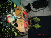
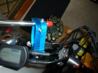
Over this weekend I succeded in powering E+ on A123 ONLY, with NMH 30 cells string opened.
As you can see on pictures display powered up normally with all functions on display working.
With throttle active I ran motor idle no load with rear wheel supported on the stand many times with power drawn shown on display.
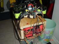
Of course I had to open front hub , disconnect NMH string of 30 cells and connect A123 instead. But it was not so simple.
When I completed connections I basically had my A123 battery monitored by Eplus NMH BMS.
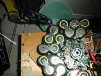
NMH BMS of E+ does not have cell level monitoring, every cell of 30 cell string is not monitored, they are monitored in group of 5 in 6 modules.
So every 5 cells have sense board connected to it which basically sense voltage of the group.
While experimenting with E+ BMS you basically want to power E+ on non-EMS battery and not to generate any error displayed on display.
It is fooling NMH BMS electronics that it is still connected to NMH cells while in reality it is connected to A123.
if it comes to A123 voltages they are pretty close to NMH voltages so electronics do not care if they are connected to NMH or A123.
Signals from sense boards which are basically voltages are fed into Microcontroller PIC18F.. Based on this voltages microcontroller "decides" about things like:
LVC is triggered for sure based on signals sent from sense boards
10-minute shutdoown happens when no change in voltages is detected /no current drawn/.
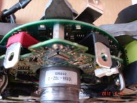
From experiments I found out that only 2 boards needs to be active/connected/ to system so it will NOT to generate error.
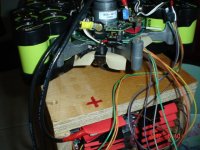
Two boards on picture are DSP board and power board sandwitched together.
Those 2 boards I will be removing front front hub and they will be incorporated into my A123 battery.
Of course DSP board must communicate with master controller inside console when you press power button on console.
Beauty of my modification is that I can have regen available immediately if I want. I doubt regen breaking on E+ is activated based on cell voltages but rather on discharge count stored in register of microcontroller. As you know regen on E+ is activated when first bar on battery SOC disappears. SOC is controlled by chip performing Columb discharge/charge count.
Once certain discharge count is registered regen breaking is activated.
All you have to do to have regen you discharge NMH before final getting rid of front hub battery.
Check out my pictures.
if you do not agree, please disagree in civilized way.
My project of getting rid of hub battery on my E+ continues.
For the first time---------
Over this weekend I succeded in powering E+ on A123 ONLY, with NMH 30 cells string opened.
As you can see on pictures display powered up normally with all functions on display working.
With throttle active I ran motor idle no load with rear wheel supported on the stand many times with power drawn shown on display.
Of course I had to open front hub , disconnect NMH string of 30 cells and connect A123 instead. But it was not so simple.
When I completed connections I basically had my A123 battery monitored by Eplus NMH BMS.
NMH BMS of E+ does not have cell level monitoring, every cell of 30 cell string is not monitored, they are monitored in group of 5 in 6 modules.
So every 5 cells have sense board connected to it which basically sense voltage of the group.
While experimenting with E+ BMS you basically want to power E+ on non-EMS battery and not to generate any error displayed on display.
It is fooling NMH BMS electronics that it is still connected to NMH cells while in reality it is connected to A123.
if it comes to A123 voltages they are pretty close to NMH voltages so electronics do not care if they are connected to NMH or A123.
Signals from sense boards which are basically voltages are fed into Microcontroller PIC18F.. Based on this voltages microcontroller "decides" about things like:
LVC is triggered for sure based on signals sent from sense boards
10-minute shutdoown happens when no change in voltages is detected /no current drawn/.
From experiments I found out that only 2 boards needs to be active/connected/ to system so it will NOT to generate error.
Two boards on picture are DSP board and power board sandwitched together.
Those 2 boards I will be removing front front hub and they will be incorporated into my A123 battery.
Of course DSP board must communicate with master controller inside console when you press power button on console.
Beauty of my modification is that I can have regen available immediately if I want. I doubt regen breaking on E+ is activated based on cell voltages but rather on discharge count stored in register of microcontroller. As you know regen on E+ is activated when first bar on battery SOC disappears. SOC is controlled by chip performing Columb discharge/charge count.
Once certain discharge count is registered regen breaking is activated.
All you have to do to have regen you discharge NMH before final getting rid of front hub battery.
Check out my pictures.
Attachments
-
 E+ powered by A123 battery 001.JPG80.8 KB · Views: 3,382
 -
 E+ powered by A123 battery 008.JPG77 KB · Views: 3,382
 -
 E+ powered by A123 battery 009.JPG84.4 KB · Views: 3,382
 -
 E+ powered by A123 battery 006.JPG83.9 KB · Views: 3,382
 -
 E+ powered by A123 battery 012.JPG63.8 KB · Views: 3,382
 -
 E+ powered by A123 battery 033.JPG69.6 KB · Views: 3,382
ambroseliao
100 kW
Great work Miro!
You are very brave for risking your working E+ system to test the A123 pack. I had a neighbor with an E+ bike visit over the weekend. It is a beautiful motor and hub!
Ambrose
You are very brave for risking your working E+ system to test the A123 pack. I had a neighbor with an E+ bike visit over the weekend. It is a beautiful motor and hub!
Ambrose
BVH
1 kW
- Joined
- Mar 26, 2009
- Messages
- 411
Yes! This is great investigative work Miro!! I also appreciate what you're doing to keep our wonderful rides alive!
Have you found the physical interface where battery power is converted to 3-Phase power for the motor? Is it in the front hub controller and is that why there are 3 terminals in the front hub battery connector? But that doesn't make sense because the same connector is used to charger the battery and that is not 3-Phase.
When you build your final A123 battery with E+ BMS components, I assume you're going to plug in at the rear connectors (both battery and Comm)?
dnmun
1 PW
ok, you removed the two 5 cell assemblies in order to get access to those two terminals, the red and black shrink colored terminals? so normally the two 5 cell packs would be bolted on to those terminals?
be very careful because if you burn up something, there is no replacement from E+. so maybe take the A123 pack back off until we can identify some of the components on the pcbs and look at how the wiring is laid out.
you said DSP, do you mean a digital signal processor board? and the other board you called 'power' and so that is the real controller board that creates the phase wire currents?
each 5 cell pack has a connector to the DSP board? when you remove power from the A123 and the other 4 packs still attached then if you can take pictures of where the 5 cell packs attach to the board so we can see where the traces run and if they connect to optoisolators (so we would need to create a signal there for the opto, or a voltage source coming back up to this DSP board from the 5V regulated voltage on the power board or this DSP board) that take a digital signal to the other side of the DSP board. they would go to some processor that monitors the opto for the LVC of each section of 5S cells. those signal may be able to be replaced by a signal we could create from another set of optos that would trick the DSP into thinking the nimh cells were still working and installed and above the LVC spec since the optos would be triggered by a false signal from a 'created' source, that source could be just one source, with the 6 separate leads to the processor pins to keep it thinking the 6 packs are still there and above the LVC. that would allow you to remove the 6 packs of nimh if you wanted to. i still wonder if you cannot keep those cells there and put your lifepo4 pack in parallel, but i think you have already decided you want to remove them.
but if the nimh stayed there, the red lug is where you would put the 20V/30V diode to isolate the nimh from the lifepo4 and the lifepo4 would bolt up right there where you have the A123 now, and the power of the 48V lifepo4 would flow at the full 58V right to the controller from that terminal. but instead of allowing the last or top of the 6 5cell packs to connect directly to that red terminal. you would attach the diode cathode to the top of that last 5 cell pack and the anode of the diode would attach to the red lug. that would block regen into the nimh pack but you would still be able to get regen to the lifepo4 pack if the controller would allow it. but i am assuming the red lug goes to the controller, or power board as you call it.
just be careful now if you have it open and really worry about shorting anything right now since you cannot get parts as you know. you really are taking a big risk like ambrose said, so be careful.
you should be able to remove the other nimh packs too and take the board free so you can take better close up photos of each side, these would be worth archiving since i doubt if anyone ever gets the opportunity to see the layout of these boards again. also record all the part numbers right away too in case you burn up a part by shorting it by accident so we have a visual record of the parts and can know what to replace them with.
maybe when we look at the power board we can see what the input voltage regulation is about and how to design it to work at the higher voltage of the 48V lifepo4 pack and if there are caps that would need replacing or mosfets that would need upgrading too. you don't even have to use the full 48V lifepo4, maybe just 14S lifepo4, 51V max. i bet all the parts would still work and we could modify the BMS for 14S from a 16S BMS and adjust the lifepo4 charger to 14S lifepo4.
or you could go lipo too but you have the A123 cells. in fact you have some extras since they forced you to buy more to get the replacements. as i recall you have 5 extra, which would get you to 17S but just 16S would leave you with the regular 48V setup of 16S BMS and charger, plus a spare cell that is known good and the other three iffies that you were worried about.
this could be the fastest E+ on the planet. the diode would protect the nimh, in fact the nimh would never really provide much current, until the lifepo4 had run down to 36V itself, and then the load would be shared between the two packs after that. fast fast fast.
way cool miro. cutting edge.
miro13car
100 kW
Dnmun
Many good points you make and advice, plenty to think about
Grrrr I assembled hub back but forgot to measure dimensions of boards,capacitor volts rating and so on.
I am on mobile had to come back home and read your post again
Thank you for contributing
Many good points you make and advice, plenty to think about
Grrrr I assembled hub back but forgot to measure dimensions of boards,capacitor volts rating and so on.
I am on mobile had to come back home and read your post again
Thank you for contributing
dnmun
1 PW
nobody else has gone this far with their E+. having good pictures will help all the guys hanging in the tidalforce google group too.
too bad that E+ did not just release all the schematics and design info as well as the parts lists when they decided to disappear.
to the refrain, "please help us, obie wan kenobie, you are our only hope"
too bad that E+ did not just release all the schematics and design info as well as the parts lists when they decided to disappear.
to the refrain, "please help us, obie wan kenobie, you are our only hope"
miro13car
100 kW
My whole purpose of all this project is ride my E+ on A123 with normal bicycle wheel in front, high quality one with
Kris King hub which can cost more than 100 dollars a piece but it lasts lifetime. With NMH hopefully going into recycling.
Regarding what I called power board which is plugged together with DSP board - it is just MOSFTES to turn off/on NMH battery I understand , nothing to do with 3-phase inverter which convert battery DC into 3phase pulses to the motor.
dnmun
1 PW
don't recycle those cells no matter what. someone will need them so keep them and sell them later to another E+ owner when their pack goes bad. same for these boards and the wheel if you swap it out. you could even post it up for sale on the tidal force group mailbot.
so the real problem is that the E+ controller will not work directly off the A123 because it needs some confirmation from the nimh controller (the DSP or power board) in order to continue operating and you just need to spoof that in order for you to use the A123?
i like the term mosftes, maybe shorten it to mofte. maybe mfty.
miro13car
100 kW
Maybe I was not clear in my previous posts but DSP board must be connected to system namely master controller inside console for Eplus system to work /so it will not generate error/ - it is obvious
DSP board communicate with that master through RS485 port
So simply DSP board will sit inside my battery probably together with power board
Can power board be removed?
That's good question
DSP board communicate with that master through RS485 port
So simply DSP board will sit inside my battery probably together with power board
Can power board be removed?
That's good question
Similar threads
- Replies
- 8
- Views
- 1,202
- Replies
- 21
- Views
- 1,114