EMC-2000 charger from ecity (1500 to 2000W)

Bazaki said:
Thanks, I did a check and I can adjust the voltage at least from 50 - 100v, lower and higher I didn't try, I was afraid to blow something up.

The FANS that were broken are fixed, but 2 of them won't do anything, no idea's of what might have been broken ?

When you say they dont work.. can you describe me that withy more details exactly..?? are they like dead?.. is the fuse blown?... do you measure Dc voltage after the bridge retifier close to teh AC input?

Doc
 
Well, the others that are connected to the 220v input do work make soft sissing noise, ( capacitors ? ) when there is no load on the output.
These 2 are completely silence, as if there is no running voltage running through anything.

The fuses are ok, both leds are working.

One of them also doesn't "click"the big relais when connecting to a battery, the other one does let the relais click.

If there is anything else I could measure/check then please let me know.
 
Bazaki said:
Well, the others that are connected to the 220v input do work make soft sissing noise, ( capacitors ? ) when there is no load on the output.
These 2 are completely silence, as if there is no running voltage running through anything.

The fuses are ok, both leds are working.

One of them also doesn't "click"the big relais when connecting to a battery, the other one does let the relais click.

If there is anything else I could measure/check then please let me know.


Please make a video of these test you make and i'll have a better idea of what it look like..

Doc
 
Doctorbass said:
...Just connect a 1K or so resistor across the two contact of this relay ( not across the coil contact!). and you should get output voltage you expect at the cahrger output...

Thus if the relay contact is permanently bypassed one could use the EMC as lab power supply with adjustable V_max and I_max ?

I have soldered a pair of cables the output contactor to bypass it external with a push button. The relay switches on if V_out > ca. 50V and it switches off if V_out < ca. 15V !

I made a few quick measurements with the two supposed voltage trimpots (V_out readings of the EMC display):
1 = W503 ; turn CW to increase V_out ;
5 = W4011 ; turn CCW to increase V_out ; shifts the range of W503, kind of offset?; I tried W503 trimming ranges for a number of fixed W4011 positions e.g. V_out range 57V - 116.5V if W4011 set to max V_out (CCW end position), 47.0-105.7V, 42.5 - 96.0, 32.5 - 73.5, 28.0 -63.5; I was able to trim down V_out to a minimum of 2V!

any other idea, how to use these two trimpots?

how do you test I_max? simply short the output? or for a given load (e.g. resistor) increase V_out till I_max is reached?

r
 
Interesting finding ! But shipping cost to Europe are very high $77: almost the same price as the charger itself ... (EMC-900 at bmsbattery.com)

Is there someone selling it in europe ? Or maybe a group order for europeans could make it ??

Flo
 
I did pay the high shipping to EU and yes the EMC900 was worth it. Managed to adjust both voltage and current thanks to you guys, BIG THANKS!!!
Not only did I install an external pot for voltage adjustment, I also made a switch that can get me from 50V (12S) to 100V (24S) in a split second, so I don't have to use the pot at all, as most of my packs are either 12 or 24S. The adjustment range of W503 is just enough to enable this by a mere bridging its two legs, which is just great.
Didn't play with the relay and V sensing so far, but overall this is a nice little (if not too little) device!
I Also ordered cheap 6fet and 9fet controllers from ecity, they work better than the infineons I had before.
 
I am thinking about buying one of these...and here in the UK we have all house 240v 13 amp + wiring. My workshop ring main circuit is good for 30 amps at 240volt, so i am good fro a 7kW charger if needed...not that I plan to go that high, probably a 4kW

What I want to know , is now a few people have been using these for a while, what is the verdict, and which voltage range unit would be best for me.
What I really mena by that is which one ..if they are different, has the best adjustable range?

I am planning my next build at the moment for the 5403, and was looking at going up to 35 series..so 145volt at 4.15.
I currently run my 5304 build at between 20 and 24 series. so 84 volt.

Will these units be adjustable to suit between 20 to 35 series??
 
NeilP said:
I am thinking about buying one of these...and here in the UK we have all house 240v 13 amp + wiring. My workshop ring main circuit is good for 30 amps at 240volt, so i am good fro a 7kW charger if needed...not that I plan to go that high, probably a 4kW

What I want to know , is now a few people have been using these for a while, what is the verdict, and which voltage range unit would be best for me.
What I really mena by that is which one ..if they are different, has the best adjustable range?

I am planning my next build at the moment for the 5403, and was looking at going up to 35 series..so 145volt at 4.15.
I currently run my 5304 build at between 20 and 24 series. so 84 volt.

Will these units be adjustable to suit between 20 to 35 series??

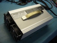
I strongly recommand you to buy one that is like 25% more voltage than you plan on using. Ex if you want 24s lipo, than ask for a charger for a voltage for 30s


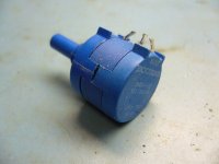
The reason is that i ordered one for 100.8V ( 24s lipo) and the max adjustable voltage i have is 105V. If i try to modify the resistor near the pot ( the one that set the max range), it dont want to go over 105V and make a strange szzzz sound indicating that it become instable( not good...).

They call them 2000W but generally, the voltage and current they offer is all product that give around 1500W.. just like mine that they wanted to set to 15A max instead of 20A... I dont care about 120V ac at 20A draw or 240V at 10A draw.. but they seem to not accept seting it for output power over 1500W.

I succeded to boose the current to up to 22A ( diring short time) at 100V... but i dont feel confident about keeping that seting continusly...

Also.. if you want to activate the output without the need of having the voltage of a battery detected, you can just connect a resistor across the relay N-O contact... 1000ohm work well and than the relay activate so you have voltage at the output.

About the max voltage they set for you i thing that the component of all teh version of that charger vary depending of the voltage you want. I think that for a given range of voltage or power, they select components according to that... in other words, i thing they have let say 4 version of charger . one that they cah adjust from 12 to 36V with the capacitor and other parts optimized for that range of voltage and current , another for 36 to 72.. adn another for 72 to 105... , another for 105 to 200... etc... due to the higher number of parallel parts for the high current version etc...

That might be the reason why mine can't go over 105V... maibe the PWM is reaching 100% at that value... so That's why i recommand you to select a voltage little higher than what you plan to use... so by that way you will be able to readjust it to your desired voltage.. and the current limit should not be too affected if you use 25% more..


Doc
 
Some pictures of my upgrade with the Cycle analyst replacing the old innacurate led display.

( i used some big dummy load resistor to show the output power ( notice i had not the perfect ohm match to reach the max power)


Doc
 

Attachments

  • P1080596_800x600.jpg
    P1080596_800x600.jpg
    94.5 KB · Views: 2,805
  • P1080597_800x600.jpg
    P1080597_800x600.jpg
    80 KB · Views: 2,805
  • P1080600_800x600.jpg
    P1080600_800x600.jpg
    81.5 KB · Views: 2,805
  • P1080605_800x600.jpg
    P1080605_800x600.jpg
    71.1 KB · Views: 2,805
Great, thanks for that.

What are the pot dials on the front? are they multi turn types? If soi , what do they connect to? a particular multiturn pot? or are they a complete unit...vernier scale and pot combined?
part number maybe?

Thanks
 
Love your work dock... are you actually using a CA just for the Vout/Aout? :shock: the dummy load resistor... that'd have to be about 150-200w ~6ohm? - again... :shock:

Any chance you can show us what pots adjust the Vout/Aout?

cheers mate...
 
Like I mentionned on the first page of the thread you can see this table showing wich pot do what...

W503 is for voltage
W401 is for end of charge current cut off adjustment
W402 is also for current adjustment ( probably the fine or coarse)
W4011 is also for voltage adjustment ( probably the fine or coarse)
W501 is for LED lamp indicator ajustment.


So i just replaced these W503 and W401 by these pot i have,

The original pot are 5kohm multiturn each.. What i did is measured the voltage range i wanna adjust and measured the coresponding resistance.

Ex, for the current, i wanted to have a range between 5A and 15A so i adjusted it to get each of these value and i measured the ohm they have for each value.

For the current i got 2.7Kohm for 5A and 780ohms for 15A...

That make a span of around 2kohm so i toke a 2kohm 10 turn precision pot ( The brand is BOURNS.. you can get some on ebay for great price)

Also i wanted to protect my charger to avoid going above 15A so i just added a little pot in serie with the main current adjust BOURNS pot that i adjusted to 780 ohm. That make impossible to get a value under 780ohm from the tow serie pot.

When the main Bourns multiturn pot is turn all the way right, i get 2780 ohm wich is close to 5A minimum. :wink:

Yes, The dial is a mechanical part that count the turn. This is also availlable on ebay. ( i got mine from one of my junk box.)

Here is what they look like.

Doc
 

Attachments

  • P1080650_800x600.jpg
    P1080650_800x600.jpg
    48 KB · Views: 2,788
sn0wchyld said:
Love your work dock... are you actually using a CA just for the Vout/Aout? :shock: the dummy load resistor... that'd have to be about 150-200w ~6ohm? - again... :shock:

Any chance you can show us what pots adjust the Vout/Aout?

cheers mate...

NOt just for the V and A out.. but also to count the Ah and Wh that goes in the battery :D 
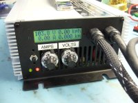
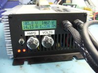
These are the best option when you want to go over 60V ( the average DC wattmeter are just rated for 60V so i needed something better :wink:

BTW, the resistor i'm using are these: 8) ( they are 4.6 ohm 1kW each cylinder for the horizontal and 2kW 1.7 ohm and 1.5kW 2.3ohm for the vertical)
 

Attachments

  • P1080652_800x600.jpg
    P1080652_800x600.jpg
    143.9 KB · Views: 2,785
Damn that looks sweet. I would kill to have my BMS bulk charger setup like that. Even if I understood how to do half the electronics, it would be literally impossible for me to get mine looking that neat. Everything I build looks like it was built by Homer Simpson...

I guess the labour would make it prohibitively expensive for you to offer, but I would buy one of those in a flash if you offered them for sale.
 
Hello I'm thinking about getting the 600W version:
http://www.bmsbattery.com/alloy-shell/27-alloy-shell-600w-lifepo4li-ionlead-acid-battery-ebike-charger.html

I'll have either 15s or 20s, so I need to adjust the voltage to 62.5V and 83V.

So to configure I have to find the W503 and adjust the voltage accordingly? I can use bazaki trick to know the voltage?
"In the mean time I did play arround some more and I found another trick, I switch on my bike, hook up the charger and let it charger, then I switch off my bike, and the charger is still in parallel with my controller, so the charger will continue with " charging" although this might be a bitt less accurate since there is some resistance from the charger, anyway it was enough to set the charger to 75,00v"

Is it as simple or did I missed something? :lol:
 
cwah said:
Hello I'm thinking about getting the 600W version:
http://www.bmsbattery.com/alloy-shell/27-alloy-shell-600w-lifepo4li-ionlead-acid-battery-ebike-charger.html

I'll have either 15s or 20s, so I need to adjust the voltage to 62.5V and 83V.

So to configure I have to find the W503 and adjust the voltage accordingly? I can use bazaki trick to know the voltage?
"In the mean time I did play arround some more and I found another trick, I switch on my bike, hook up the charger and let it charger, then I switch off my bike, and the charger is still in parallel with my controller, so the charger will continue with " charging" although this might be a bitt less accurate since there is some resistance from the charger, anyway it was enough to set the charger to 75,00v"

Is it as simple or did I missed something? :lol:


Please read the entire thread.. just 3 pages.. you will find how to activate the output without connecting a battery :wink:

( just connect a momentanous bypass to the output relay :wink: ) and it will activate ( toggle)
 
Sorry I've seen this part but I don't understand everything. What is a momentum bypass? How do I connect 1K resistor? :oops:

NeilP, I'm not even sure what I'm talking about :lol:
 
Doc means a switch that does not latch on...like a sprung loaded switch, it just comes on for a moment when the switch is activated. This fires up the relay, and puts the output out to the terminals.
 
NeilP said:
Doc means a switch that does not latch on...like a sprung loaded switch, it just comes on for a moment when the switch is activated. This fires up the relay, and puts the output out to the terminals.


Yes... exactly!
 
My brain has finally kicked in to gear..the word Doc was looking for was 'Momentary'

As for where to get the switch...well any of the online electronics retailers..Mouser, RS Export, Maplin / Radio Shack/ Farnell...manuy others


Or maybe even your local hardware store...basically it is a door bel type switch, does nto need to be particularly high current, it is jsut to latch the relay open, and once this happens, and voltage is otn he output side, then that keeps the relay open .
 
This is a great thread - needs to go back up top. I think I am going to order a few of these and try some mods of my own.

Good job doc - and I really like the CA modification. I always include a CA in with my load stations, it makes life real easy.

IMG_20120117_161951.jpg

-methods
 
Doc, Methods..

I e-mailed Justin many weeks ago, and did suggest to him that it would be great if they marketed a CA, as an an e-bikes.ca power meter for charging and discharging purposes. I currently use one in the same way on my PC PSU charging station

He did tell me that something like that is on the agenda already..Absolutely no time scale at present, but the idea was there.
So one day we may have an e-bikes.ca C(D) A .... Charge (Discharge) Analyst
 
Does BMSBattery configure the charger for us? There are a form for that:
Screen%20shot%202012-01-18%20at%2017.25.46.png

http://www.bmsbattery.com/alloy-shell/27-alloy-shell-600w-lifepo4li-ionlead-acid-battery-ebike-charger.html

I've put 62V (for 15s) and 83V (for 20s). Can I select the required voltage after?
 
Back
Top