The Road to Higher HP 100-200-500+ HP

Basically once the engines and fuel tanks are gone the Roadrunner won't weight much more than a newer Miata would at such point in a conversion, while offering much more room for lots of batteries. Where would you put them in a Miata?
 
How hard would it be to test out running multiple controllers on a multi phase motor? I know with the 6phase motor i have from johns that its using 2 seperate sets of halls, how hard would it be to determin where the extra hall placement should be? Could it be tested on a rewound crappy hub motor which has more then enough teeth to wind probably 4 seperate 3-phase setups into one motor? Run it with 4 350w cheapy controllers to see how well it works. I know efficiency would take abit of a hit with out working everything out but it would be interesting to see if it works. Then its just a matter of finding a huge motor like Arlo is playing with but with a high number of poles etc. Atm 30-40kw seems to be the max attainable on "cheap" controllers. 15 controllers ~ 450kw+, its only 45phases :roll:

I dont know much about winding motors but is it possible to wind a motor only using 1 tooth on each side per phase or do u have to use 2 teeth per side winding clock wise and counter clockwise?
 
I was thinking the TI Picolo TMS320F2806 because :
1. You can load TI InstaSpin on it to get up and running fast to prove out the hardware
2. You can later remove InstaSpin and put in your own software once hardware is proven, but i am worried not enough PWM outputs? looks like 8?
3. You can simulate this controller in Proteus which would be great for learning purposes (I am very interested in learning how to code for motor control)
4. TI comes with amazing support & lots of quality web resources
 
HighHopes said:
just to put things into perspective.. the 100HP rated continuous Hyperpack from Infioneon costs $5K. so, 500HP would cost .. 25K? so if you build yourself maybe cost 10K? and that's if it works the first try? i dunno man.. seems like a big risk. the design & software part is not a big deal because its just on paper but eventually you'll want to give it a go. hope you have some deep pockets :!:
Yeh but on the other hand I got 7 800 amp 1200 volt igbts for $200...
This doesn't need to happen over night. New tech will come and I plan to build the motor to know its good for the numbers I want. As well this is a intermittent rating I would say 500hp for 30seconds or a minute. maybe 1000HP for 10 seconds for a absolute limit.
I will start with the smaller 20 HP induction motor converted to hopefully ~150-200hp for a 30second number and even with it I can just power one section of the motor to start then as I get more money add more sections. Start small with a cheep 24 mosfet controller from my bicycle then make the car move and work up from there.
I hope to start building motor casings and rotors this winter but there is no rush. I'm stuck learning FEMM right now in my very little spare time.
 
Bluefang said:
How hard would it be to test out running multiple controllers on a multi phase motor? I know with the 6phase motor i have from johns that its using 2 seperate sets of halls, how hard would it be to determin where the extra hall placement should be? Could it be tested on a rewound crappy hub motor which has more then enough teeth to wind probably 4 seperate 3-phase setups into one motor? Run it with 4 350w cheapy controllers to see how well it works. I know efficiency would take abit of a hit with out working everything out but it would be interesting to see if it works. Then its just a matter of finding a huge motor like Arlo is playing with but with a high number of poles etc. Atm 30-40kw seems to be the max attainable on "cheap" controllers. 15 controllers ~ 450kw+, its only 45phases :roll:

I dont know much about winding motors but is it possible to wind a motor only using 1 tooth on each side per phase or do u have to use 2 teeth per side winding clock wise and counter clockwise?
I think this is easy to test but I would only use one brain or if you do use multiple controllers then only 1 set of halls. You don't want the hall timing off at all from one set of phases to the other.
Highehopes said:
but i am worried not enough PWM outputs? looks like 8?

I keep saying its just added powerstages. Only one brain. If you have 60 stator teath and say you want to split it to 2 3phase sections you take the 6 pwm outputs from the 1 brain and run the 6 pwm outputs to both powerstages or if you have 4 sets of 3 phase sections you run the 6 sets of pwm outputs to all 4 powerstages.

Now to to this we might need a buffer section that can up the current from the main brain output this will depend on how many powerstages you want to run and your driver chip draw as well as the current output capabilities of the brain board.
 
I'm stuck learning FEMM
what software are you using?

1 brain and run the 6 pwm outputs to both powerstages
well, we agree on 1 brain. :)
the 6 pwm outputs going to both power stages is a similar argument to having only 3 current sensors. my counter argument is the same in principle, i think it is less reliable and lower (slightly) performance to have the second power stage as a pure slave unit. i'm not saying it can not be done.. it just goes against my philosophy so it is not an idea i am comfortable with.

the nice part about your plan is that you can use the lebowski controller which you already know well. don't worry about driving multiple power stages, one can always use some fan-out logic if needed. its not the way i would do a muliphase machine for EV application but who knows, maybe you will be very successful :)
 
HighHopes said:
I got 7 800 amp 1200 volt igbts
can you send me the part number?
1mbi800u4b-120

http://www.alldatasheet.com/datasheet-pdf/pdf/217729/FUJI/1MBI800U4B-120.html
 
Arlo1 said:
HighHopes said:
I got 7 800 amp 1200 volt igbts
can you send me the part number?
1mbi800u4b-120

http://www.alldatasheet.com/datasheet-pdf/pdf/217729/FUJI/1MBI800U4B-120.html
Coming back to this... IM looking at splitting phases also to keep the voltage lower so IM going to see where I can get with 100-200v rated mosfets.
IM just using the IGBTs as an example for cutting cost. I know you come from Cost doesn't matter type designs but sometimes finding a mosfet on a budget matters like sevcon who uses is it 96?? IN the size 8? Its a very large number and they have a very reliable controller from what I herd just a PITA to program.
 
i think that IGBT is not meant to switch at high frequency cause the switching time is long and the energy ON/OFF is high. i'm thinking 5kH to 10kHz at most. i think that might not match well with your low inductance motor.
 
HighHopes said:
i think that IGBT is not meant to switch at high frequency cause the switching time is long and the energy ON/OFF is high. i'm thinking 5kH to 10kHz at most. i think that might not match well with your low inductance motor.
No not at all. But the inductance will increase at a square of the amount of windings you add. So if its a 4 turn now with 8uh inductance with a kv of 75 75rpm/volt and you wind it for 4x the voltage it will be 18.75kv (7500 unload rpm at 400 volts.) It will be 128uH inductance.

I bought them with this in mind. But since I have proven I can do with out the danger of the hi voltage.
:Edit also coming back to this. With split phases the inductance will also be higher as seen by every power stage making fet or igbt selection a little easier.
 
Looking back at the Colossus project, I think what we take as a learning from that is that it is difficult to manage the spikes in the system. Spikes come from the circuit/wiring inductance combined with high current (spike energy is .5*L*I^2).
A differently wound motor will have more voltage and lower current, but the same circuit inductances. Even though the motor inductance is different (more windings), the layout of the power bus and wiring remains the same. So, a high voltage low current system will have lower spikes than a similar power low voltage high current system.

If you look for instance at the motors sold by ABB for use in trams and trolley busses, they all top out at around 50A or so, but at 1500 V ....
 
Lebowski said:
Looking back at the Colossus project, I think what we take as a learning from that is that it is difficult to manage the spikes in the system. Spikes come from the circuit/wiring inductance combined with high current (spike energy is .5*L*I^2).
A differently wound motor will have more voltage and lower current, but the same circuit inductances. Even though the motor inductance is different (more windings), the layout of the power bus and wiring remains the same. So, a high voltage low current system will have lower spikes than a similar power low voltage high current system.

If you look for instance at the motors sold by ABB for use in trams and trolley busses, they all top out at around 50A or so, but at 1500 V ....
Yes and I was heading in that direction but I have decided I want to try splitting sections of the motor... And it just so happens I have a spare colossus to do this with. IN fact I wound one half separate from the other then terminated outside the case so I can experiment.
 
with 1200V rated IGBT that can be used for max 600V DC bus which is 347V AC line-to-line. this is a typical motor voltage in canada by the way.
with a 350HP motor at this voltage your phase current would be about 477A with peak of 675A which is probably max that your IGBT can handle assuming liquid cooling.

the switching frequency will become important because it directly ties between performance (squealing tires and fast acceleration) and losses in the IGBT. if the losses are too high and you do not want to sacrifice performance, then you have to lower the power level. so there is a balance here to be considered.
 
As far as batteries go, I have 20 5ah 6s nanotech packs. They are 75 bucks each shipped. Whole pack weighs 33lbs and around 1600 bucks for duds, wiring etc... this pack reliably outputs 420A while sagging from 94 to 87v. 87v at 420A is almost 50hp at the terminals. Ten of those around 16k and 350lbs isn't too unreasonable. Would LOVE to see a muscle car with that many nanos in it lol.
 
HighHopes said:
with 1200V rated IGBT that can be used for max 600V DC bus which is 347V AC line-to-line. this is a typical motor voltage in canada by the way.
with a 350HP motor at this voltage your phase current would be about 477A with peak of 675A which is probably max that your IGBT can handle assuming liquid cooling.

the switching frequency will become important because it directly ties between performance (squealing tires and fast acceleration) and losses in the IGBT. if the losses are too high and you do not want to sacrifice performance, then you have to lower the power level. so there is a balance here to be considered.

First and for most IM not planning to use the IGBTs ATM the plan is for mosfets..... Thats the whole reason of the multi phase motor. Maybe ixfk230n20t they are a good part from what I have tested so far.

Second 600v dc bus is 347 line to line??? If you spin a motor up to where the back emf matches the DC bus (only happens unloaded) you will have DC voltage at the peaks from phase to phase with a PMAC BLDC PMSM motor are you talking Induction motor?
 
Farfle said:
As far as batteries go, I have 20 5ah 6s nanotech packs. They are 75 bucks each shipped. Whole pack weighs 33lbs and around 1600 bucks for duds, wiring etc... this pack reliably outputs 420A while sagging from 94 to 87v. 87v at 420A is almost 50hp at the terminals. Ten of those around 16k and 350lbs isn't too unreasonable. Would LOVE to see a muscle car with that many nanos in it lol.
IM not sure on this part yet like I said I will build it and add batteries later. But a hybrid pack with enough thunderski or something good for lots of life cycles might be what the main pack is then a nanotech pack parallel for the added amps needed for a drag race.
 
Talking about testing the multiple controllers out with a hub motor how would you wind it assuming you were keeping it as simple as possible.

6 pole motor with a normal winding would be ABCABC

12 pole motor with 2 controllers which would be the one to use
ABCDEFABCDEF. ABC been one controller and DEF been the other
or
ADBECFADBECF

I am keen to test this out as with the 6phase motor i have from John it uses 2 seperate hall sensor groups so wouldnt that indicate that something is abit different? Also how many controllers could a single set of halls trigger? To keep it cheap off the shelf controllers are still going to rule as much as we all wish for custom multi phase controllers.
 
With building the inrunner core for use with the rewound induction motors would something similar to https://endless-sphere.com/forums/viewtopic.php?f=30&t=14264

Before the thread owner disappeared at the end he talked about the motor running "with more torque then it used too". Unfortunately it tapers off there with one of the last comments about how one of the magnets managed to rotate itself which could have stopped the motor/killed the controller in the first place and how he was getting a sensored controller. Unless i am missing something its a workable idea as machining a core like that one was done on a normal drill press so a hobbyist could do it with fairly easily accessible tools.
 
Bluefang said:
With building the inrunner core for use with the rewound induction motors would something similar to https://endless-sphere.com/forums/viewtopic.php?f=30&t=14264

Before the thread owner disappeared at the end he talked about the motor running "with more torque then it used too". Unfortunately it tapers off there with one of the last comments about how one of the magnets managed to rotate itself which could have stopped the motor/killed the controller in the first place and how he was getting a sensored controller. Unless i am missing something its a workable idea as machining a core like that one was done on a normal drill press so a hobbyist could do it with fairly easily accessible tools.
Yeah the plan is for this to be a DIY hobiest type design. IM now estimating the big motor in FEMM.... But I don't know how to do any of it properly... SO I will need some help/time.
 
IM now estimating the big motor in FEMM.... But I don't know how to do any of it properly... SO I will need some help/time.

what software are you using?
 
Bluefang said:
Talking about testing the multiple controllers out with a hub motor how would you wind it assuming you were keeping it as simple as possible.

6 pole motor with a normal winding would be ABCABC

12 pole motor with 2 controllers which would be the one to use
ABCDEFABCDEF. ABC been one controller and DEF been the other
or
ADBECFADBECF

I am keen to test this out as with the 6phase motor i have from John it uses 2 seperate hall sensor groups so wouldnt that indicate that something is abit different? Also how many controllers could a single set of halls trigger? To keep it cheap off the shelf controllers are still going to rule as much as we all wish for custom multi phase controllers.

That motor is ABC wound on every other tooth, and then DEF on the open teeth.
 
Another option would be to take the normal winding pattern and work it out so that for the corresponding 3 points you wind a controller with the normal A CE and a CCW But instead of 4 a's in a row you have 4 separate controllers.

Would separating the windings work like that?
Or am I heading in the wrong direction? :mrgreen:
 
HighHopes said:
IM now estimating the big motor in FEMM.... But I don't know how to do any of it properly... SO I will need some help/time.

what software are you using?
http://www.femm.info/wiki/HomePage
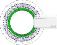
IM just learning it. I was able to play with numbers and get 2500nm torque with 10 turns of aluminum on each tooth with 1000 amps flowing though it. But im way out on how to set this up so.... Just hoping for a 500-800 continuous with oil cooling and depending on max rpm because I will need enough RPM for the HP to come up.
 
Managed to find big numbers with 10 turns of 14 awg and 500 amps per phase A and B enegized (WYE wound) C off 20 magnets... But I'm so not sure im doing it right....
At 100 amps its 70nm at 500 its 970 and at 1000 its 2500nm....?? WHF.
I also tried 10 magnets... I have tried 1 turn of aluminum and no luck so far making it worth while.
 

Attachments

  • femm (800 x 628).jpg
    femm (800 x 628).jpg
    88.6 KB · Views: 1,238
Back
Top