The Road to Higher HP 100-200-500+ HP

That sounds like a very interesting amount of torque :mrgreen: 1000amps would be very very do able if we can use multiple power phases/controllers. I think you said it was 48 teeth, that would be 8 controllers/lots of 3 phase connections.

I have almost go my hands on a small 1/4hp AC motor to test out and see if its as easy as i think it will be to run multiple controllers on a single motor and see if i can build a inrunner core similar to the one in the thread i linked. One idea i have had for the smaller inrunner core would be to 3d print it out of nylon as a test, hopefully use square magnets so i can mount them all up and then vacumm impregnate the whole core with a expoxy to add alot more strength and heat resistance. I have a friend with a large lath so i can smooth the center bore and outside to match the diameters needed and balance the core.

Weird ideas, no idea if any of it will work but i have never been one to plan it out. I could never learn Femm to do the design properly so keep up the great work with everything Arlo and sorry if i am moving your thread off track abit.
 
Bluefang said:
That sounds like a very interesting amount of torque :mrgreen: 1000amps would be very very do able if we can use multiple power phases/controllers. I think you said it was 48 teeth, that would be 8 controllers/lots of 3 phase connections.

I have almost go my hands on a small 1/4hp AC motor to test out and see if its as easy as i think it will be to run multiple controllers on a single motor and see if i can build a inrunner core similar to the one in the thread i linked. One idea i have had for the smaller inrunner core would be to 3d print it out of nylon as a test, hopefully use square magnets so i can mount them all up and then vacumm impregnate the whole core with a expoxy to add alot more strength and heat resistance. I have a friend with a large lath so i can smooth the center bore and outside to match the diameters needed and balance the core.

Weird ideas, no idea if any of it will work but i have never been one to plan it out. I could never learn Femm to do the design properly so keep up the great work with everything Arlo and sorry if i am moving your thread off track abit.
First off don't get excited about the numbers. Because I don't think they are real. I need help and nobody can help me lol. I looked for a femm forum with no luck and I posted in the "using femm" thread with no response yet. Thing is there is a lot to learn with femm and I might have some settings wrong. I have no clue how to tell when saturation is found.

Second off its a 60 tooth stator and I know I can make mutilple power stages run the same motor. This is like having multiple controllers but easier to run and more reliable and cheaper. Using separate compleat controllers you will have the risk of one firing at the wrong time if you have one false event ie a hall timing off on one controller or a sensroless false trigger BAM everything might be toast in both or all controllers. I am planning evenly spaced magnets and stator teeth to be aligned on different sections of the motor at the same time so each section that's aligned at the same time can all be sent the same PWM signal from the master controller! The only downfall to this is current ripple from the battery.
 
Arlo1 said:
I have no clue how to tell when saturation is found.
You need to specify the material (BH curve). When the flux density is higher than the knee, it is saturated.
220px-Magnetization_curves.svg.png

Magnetization curves of 9 ferromagnetic materials, showing saturation. 1.Sheet steel, 2.Silicon steel, 3.Cast steel, 4.Tungsten steel, 5.Magnet steel, 6.Cast iron, 7.Nickel, 8.Cobalt, 9.Magnetite
from: http://en.wikipedia.org/wiki/Saturation_%28magnetic%29
 
gwhy! said:
http://www.treehugger.com/cars/electric-mini-0-60-in-4-seconds-it-has-motors-in-its-wheels.html

that's from August 30, 2006


the sad thing is... I can remember when it was done !


even sadder... we haven't come that far in the last 7 years :(
 
Lebowski said:
I disagree, electric bikes have become mainstream here in Europe over the last 7 years...

I was thinking more about cars, hub motors for cars sound like a great idea, but there's not many around, they make it easy for anything to be a hybrid

can't see anything in that report, but I'm sure the battery was some kind of lithium chemistry... batteries have improved... but not by that much

I mostly said it because I can remember reading that 7 years ago and thinking things were starting to pick up, and pretty soon electric cars would be main stream.. or 'normal' anyway
 
knighty said:
gwhy! said:
http://www.treehugger.com/cars/electric-mini-0-60-in-4-seconds-it-has-motors-in-its-wheels.html

that's from August 30, 2006


the sad thing is... I can remember when it was done !


even sadder... we haven't come that far in the last 7 years :(


I know the reasons way it has not been heard of since :(

But the company that makes the hubs do exist http://www.pmlflightlink.com/ but dont never hear much about these monster hubs :?:

edit: I know the guy that made the custom exhaust for the small genny in the boot..


http://www.worldcarfans.com/10607246585/pml-builds-640hp-electric-mini
 
major said:
Arlo1 said:
I have no clue how to tell when saturation is found.
You need to specify the material (BH curve). When the flux density is higher than the knee, it is saturated.
220px-Magnetization_curves.svg.png

Magnetization curves of 9 ferromagnetic materials, showing saturation. 1.Sheet steel, 2.Silicon steel, 3.Cast steel, 4.Tungsten steel, 5.Magnet steel, 6.Cast iron, 7.Nickel, 8.Cobalt, 9.Magnetite
from: http://en.wikipedia.org/wiki/Saturation_%28magnetic%29
Thanks major. Have you worked with FEMM?
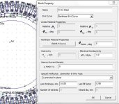
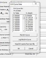
Here is what I have it set to...
 

Attachments

  • BH curve.JPG
    BH curve.JPG
    65.9 KB · Views: 1,456
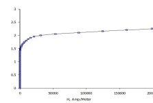
I think its all set ok. I plotted the numbers and seems right. But maybe the air gap is to big in my simulation?
Here is the Using femm thread
 

Attachments

  • BH curve 2.JPG
    BH curve 2.JPG
    37.3 KB · Views: 1,462
  • BH 3.JPG
    BH 3.JPG
    18.6 KB · Views: 1,462
Miles said:
Arlo,

The laminations are 0.635mm thick?

If they are the only part you're re-using, I think you might as well start from scratch....
I think so. They are hard to measure. But I priced lams out and for diy its ridiculous.
I have to find my info I gathered with the scooter build and see what kind of surface speed the magnets can have with a certain lamination thickness.
 
Arlo1 said:
I have to find my info I gathered with the scooter build and see what kind of surface speed the magnets can have with a certain lamination thickness.
It's not directly related to surface speed, it depends on the fundamental frequency the motor is used at. Rule of thumb is 400Hz for 0.35mm laminations. The eddy current losses go up as the square of the lamination thickness.
 
Yup I need to mesure them again because .025" is pretty thick. I found a max realistic rpm with my custom stator to be ~9000 rpm with a 4 inch rotor so that's ~ 3500 with the 10 inch rotor I will be building.
http://endless-sphere.com/forums/viewtopic.php?f=2&t=28748&hilit=scooter&start=25
Does FEMM help estimate the max rpm vs eddy currents as well?
 
Miles said:
Arlo1 said:
I have to find my info I gathered with the scooter build and see what kind of surface speed the magnets can have with a certain lamination thickness.
It's not directly related to surface speed, it depends on the fundamental frequency the motor is used at. Rule of thumb is 400Hz for 0.35mm laminations. The eddy current losses go up as the square of the lamination thickness.
Are you sure? I would love to just change the pole count and rewind the motor for the scooter and bring that back to life.

I though eddy currents were from the magnet passing the metal faster the speed the more the currents.... I though hysterias was dependent on pole count not the eddy currents.
 
Hysteresis losses are directly proportional to the fundamental frequency. Eddy current losses go up as the square of the fundamental frequency, I'm afraid....

http://www.endless-sphere.com/forums/viewtopic.php?p=603206#p603206

Given all of these issues, core loss prediction using relatively simple modeling mayindicate the correct trends from one motor design to the next but will not likely pro-duce accurate estimates of core losses at any given operating point.Using knowledge of the fundamental principles that cause core losses, they can bereduced by:

• Reducing the lamination thickness. Ideally, eddy current losses are directlyproportional to the square of the lamination thickness. Therefore, if lamina-tion thickness is reduced by a factor of two, eddy current losses decrease bya factor of four.

• Increasing the resistivity of the lamination material. Eddy current losses areinversely proportional to material resistivity. Adding silicon to laminationsteel is the most commonly adopted approach to increasing material resis-tivity.

• Annealing laminations after they have been stamped or cut. This eliminatesthe influence of mechanical stress on core loss.

• Reducing the amplitude of the magnetic field within the material. Hystere-sis losses are directly proportional to the amplitude of the magnetic fieldraised to a power between 1.5 and 2.5. Eddy current losses are directly pro-portional to the square of the magnetic field amplitude. Using this propertyto reduce core loss is in direct conflict with maximizing torque production.As a result, other techniques for minimizing core losses are often imple-mented first.

• Reducing the number of magnet poles Nm. Hysteresis losses are directlyproportional to the fundamental electrical frequency. Eddy current lossesare directly proportional to the square of the fundamental electrical fre-quency. Since the fundamental electrical frequency is Nm/2 times greaterthan the motor shaft speed, reducing the magnet pole count allows one toreduce core losses significantly without lowering the motor shaft speed.
 
Arlo, great project man. Don't worry about spending a shit-ton of money. As long as you learn something and it's fun, it will be worth it. I will have spent over $43,000 on my race bike by the time it's done. Nothing on the budgets of Michael Czysz and the like, but substantial nonetheless. Sure, its more of an assembly, but the way they get put together is the key.

I am going to keep an eye on this thread as I would like to drop a motor identical to the Evo AFM-140 into the CRX. I think the bike deserves its own motor for the long haul, especially since the frame was built around the motor. Building a 150+ kW motor from scratch sounds like a lot of expensive fun; I'm in :mrgreen: . I'll need at least 250 and preferably 300 Nm of continuous torque and 5000 rpm for a direct drive to be worth pursuing. The big question though - Axial flux or radial?

Not sure if I want to design my own controller though. That's hard, and involves things I still don't understand, like how integrated circuits work.
 
Miles said:
• Reducing the number of magnet poles Nm. Hysteresis losses are directlyproportional to the fundamental electrical frequency. Eddy current lossesare directly proportional to the square of the fundamental electrical fre-quency. Since the fundamental electrical frequency is Nm/2 times greaterthan the motor shaft speed, reducing the magnet pole count allows one toreduce core losses significantly without lowering the motor shaft speed.
[/quote]
Don't be "afraid" because this is gold right here! Thanks miles. Now I just need to figure out how to get a rough idea what I can accomplish. First I need to figure out what magnet securing scheme I will use then I need to see what kind of realistic max rpm I can have. I'm hoping for a 5000-6000 rpm with that at a hope full 800 ft/lbs torque I can get my 500+ HP goal.
 
jonescg said:
Arlo, great project man. Don't worry about spending a shit-ton of money. As long as you learn something and it's fun, it will be worth it. I will have spent over $43,000 on my race bike by the time it's done. Nothing on the budgets of Michael Czysz and the like, but substantial nonetheless. Sure, its more of an assembly, but the way they get put together is the key.

I am going to keep an eye on this thread as I would like to drop a motor identical to the Evo AFM-140 into the CRX. I think the bike deserves its own motor for the long haul, especially since the frame was built around the motor. Building a 150+ kW motor from scratch sounds like a lot of expensive fun; I'm in :mrgreen: . I'll need at least 250 and preferably 300 Nm of continuous torque and 5000 rpm for a direct drive to be worth pursuing. The big question though - Axial flux or radial?

Not sure if I want to design my own controller though. That's hard, and involves things I still don't understand, like how integrated circuits work.
Thanks.

With what I have built in the last 3 years. I can say bringing an electric motorcycle to market is NOT EASY! I'm not trying to bring one to market but I can only imagine what the guys at Brammo and Zero etc. go though! I think once you spend the time to figure out what works for you for a motor then its not so bad to build a motor from scratch. IM not worried about spending money lol. I just don't have much.
 
Arlo1 said:
Thanks miles. Now I just need to figure out how to get a rough idea what I can accomplish. First I need to figure out what magnet securing scheme I will use then I need to see what kind of realistic max rpm I can have.
It's all about choosing your compromise (including the cost!) Reducing the number of poles will reduce parasitic losses but increase active (copper) losses......
 
Miles said:
Arlo1 said:
Thanks miles. Now I just need to figure out how to get a rough idea what I can accomplish. First I need to figure out what magnet securing scheme I will use then I need to see what kind of realistic max rpm I can have.
It's all about choosing your compromise (including the cost!) Reducing the number of poles will reduce parasitic losses but increase active (copper) losses......
I'm really trying to see if I can make it a solid slot motor.
 
Miles said:
Arlo1 said:
I'm really trying to see if I can make it a solid slot motor.
Which pulls you in the direction of a greater pole count......
I was thinking I could make over lapped windings with solid slot or not even over lapped but use say six or 8 slots to do 3 or 4 turns and have one long N or S magnet that its lined up to all the slots at once. I am experimenting in femm with it now.
 
Arlo1 said:
OK So I will start this way.... I have a 1969 Road Runner. I don't use it. Burning $100-$200 a night in fuel is not fun to me all it does is help some oil tycoon get more spoiled.
Hi Arlo,

Convert it to methanol. Get your own wood still. Make your own race fuel. 8)

Oh, and bump the compression up to 15:1 while your in there :twisted:
 
Back
Top