Hi
flute2k3@hotmail.com said:
the up and down mosfet turn on and off at the same time, hope all your mosfets are lucky to survive.
The driver has protection against both mosfets on at the same time - so all should be OK (I assume - were they?).
Also that's why the output was 0 all the time.
flute2k3@hotmail.com said:
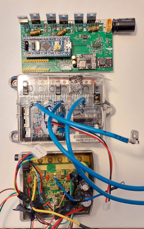
I'm going to design a fit-in-box version of PCB based on your great work, will keep posted for my progress here.
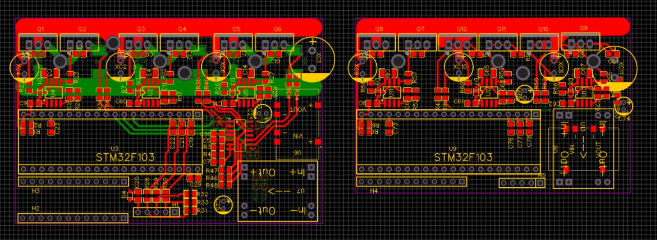
We made / are making some changes to the schematic too. maybe you want to wait for the new schematic before starting your PCB design. There are some fixed issues and some improvements.
This is also doubly true for the PCB where the schematic changes need to be implemented, and there need to be some layout changes, especially in the power stage.
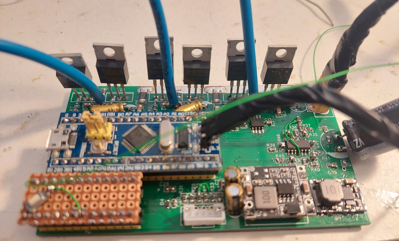
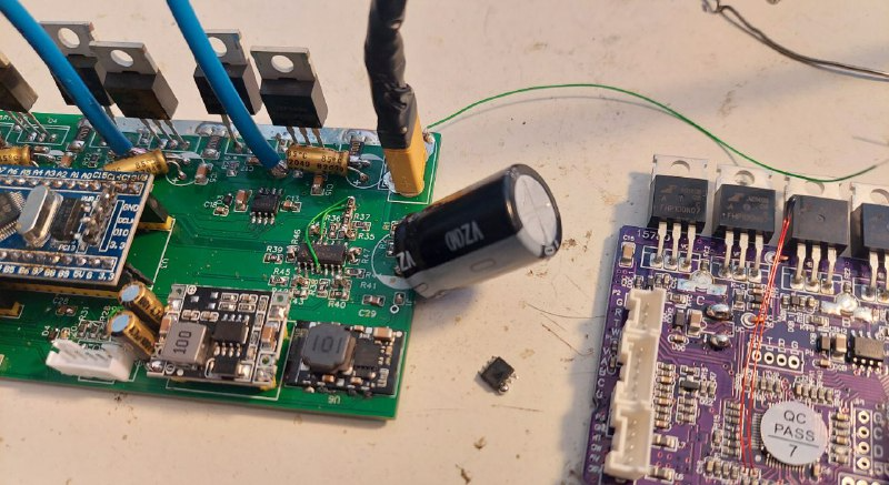
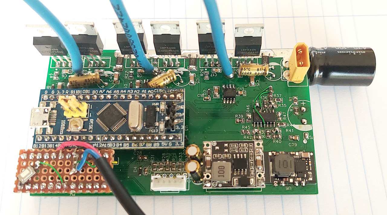
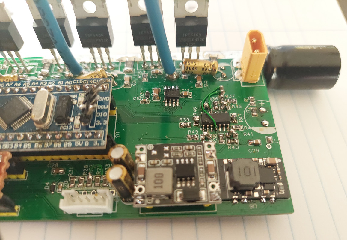
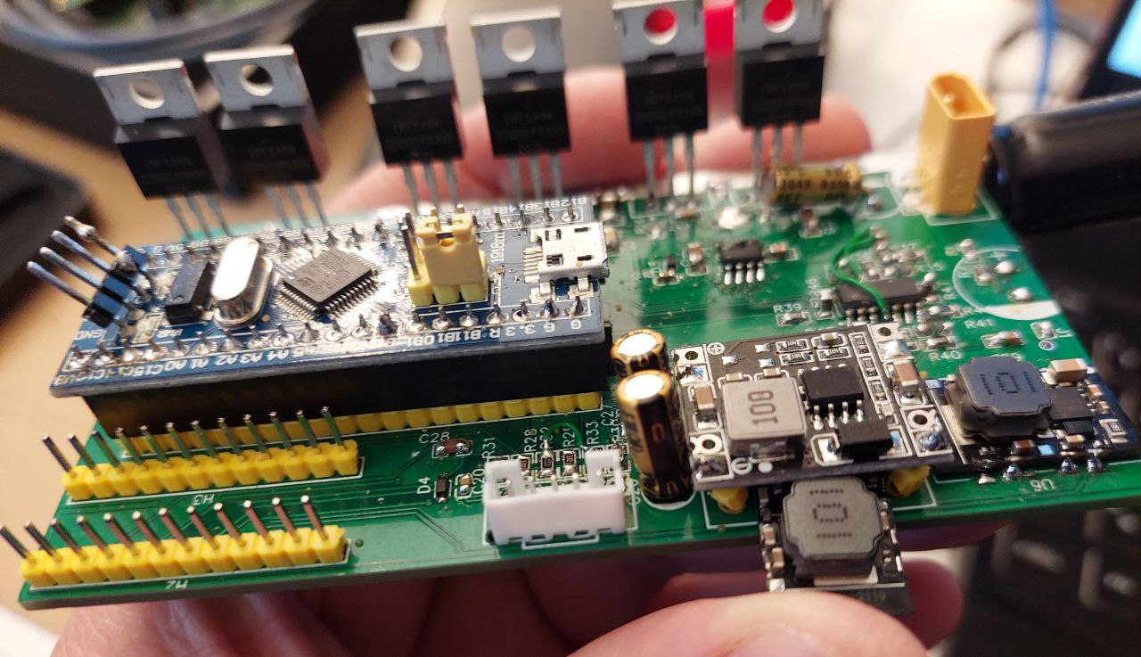
-> the big CAP (C24 in the image) was far away from the battery wires, gnd was routed to it via long thin traces. It should be as close as possible to the battery wires, or else it can't perform its function. In the part placement I posted earlier this is already fixed
-> the smaller caps (C5 C7 in the image for example) are also connected to the shunt, when they should be connected to the ground! (schematic change).
casainho said:
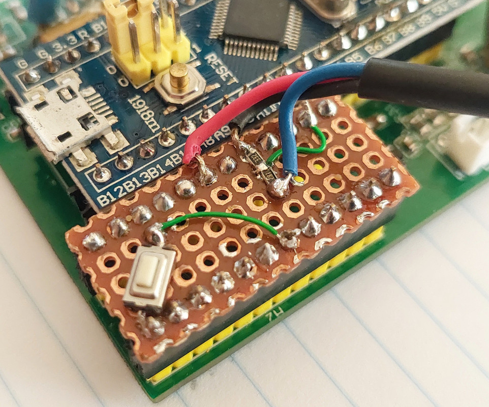
I did a short circuit on the PWM pins at the mosfet driver and the STM32F103 did burn - it was quick to repair, just removed the Bluepill with the burned STM32F103 and used a new one
Oh, the beauty of modularity!
")
Br,