Another No Solder/Weld 18650 Build (Updated 03/09/2014)

tomjasz said:
agniusm said:
Perhaps that experience is nothing to you and you tend to chase the cheapest stuff you can get but that does not make its the right stuff.
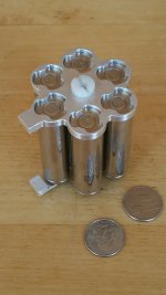
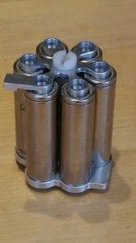
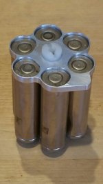
You say learn and experiment, design. There is no design here. Take 18650 holders, put some conductive inserts with dimples in them, cells, bang with hammer and ziptie them and your done. Thats it. I am continuing working on Snath design and LFP was talking about compression and material choice to keep cells in good contact all the time and my vision is towards these guys who done incredible.
Maybe you cant test mine at the moment, perhaps it is because you wont have to, cause thats my work to make sure battery is safe as i can get it. Thats why i dont force it, its because i want it solid and tested properly.
Anyway, for 19usd, i cant beat that.

When did I EVER indicate that was my feeling or intention? I'm willing to try alternatives to you product simply because yours and quality products like it are UNOBTANIUM. One bike maker tried to introduce a similar design, and it was expensive. I wanted it regardless of the price. Since then only two products have appeared that are for sale. This and the battery blocs, that's it. Why get o fired up? He's not taking anything away from your work, and again, your fantastic design is not available. I've written before on numerous occasions, I'm in whenever you're ready. It's looking REALLY GOOD. But in the meantime here comes a youngster with an idea, he works tirelessly, communicates instantly, and wants to improve. That's the spirit of ES, just as much as your project. Don't like the idea? I get that but Don't get the attack or attempts to demean someones ambition.

Thank you so much for the kind words Sir. Appreciate it !.
 
How would this rate for current flow, assuming connections can handle load.
 

Attachments

  • 20170419_110126-907x1612.jpg
    20170419_110126-907x1612.jpg
    134.3 KB · Views: 4,017
randyc1 said:
How would this rate for current flow, assuming connections can handle load.
You will trash a few 18650s and have a nice 15 minute heater, but the Polish - Indian love will endure forever. :lol: :lol: :lol:
 
Hi, the 20.2 pitch version is completely scalable, have parametric model for it, you can also build it up with normal nickel ribbon.

The 19.5 pitch version with 60° angle is another thing, much more complicated to design as it can not have spacers in between cells, but it is also much more compact. My test bike uses a 10S6P version since January at 60A peak. (here https://endless-sphere.com/forums/viewtopic.php?f=6&t=86981)

I think solderless has a enormous potential for the DIY market, especially if we send the kit pre-wired with bms already...screenshot-cad.onshape.com 2017-05-13 11-13-39.png


Testing new materials next week then I can prepare some samples to interested people.
 
bzhwindtalker said:

Testing new materials next week then I can prepare some samples to interested people.

Is there any Thread or more Infos about this Project, I'm really interesed in that Design....looks great also for my Purpose. Do you mill, 3dprint, or mold those Parts ? and how to the copper connector get pressed on the cells?

So Adam you are building thos kind of Packs for your LMX allready, or is it still "in developement" ?
And the Pack you use right now is the 19,5 pitch 60° Angle ? any troubles with to rough vibrations, or crashes?

bzhwindtalker said:
The 19.5 pitch version with 60° angle is another thing, much more complicated to design as it can not have spacers in between cells, but it is also much more compact.

I was thinking of such an project once too, i found out that with a bit more than 20 pitch and 60° angle it would be possible to fit a M3 screw between the cells, and still you'd get much more compact packs then.
(What size of screws do you use to press those "honeycomb-plattforms" together ?)

greets Notger
 
My 10s6p is CNC machined from nylon, for the 20.2mm version I tested machining in lexan but the stock was too flexible and I did not manage to hold the z levels.

So now working on finding and testing 3d printing material with the best heat and flame characteristics and printing ease.

This kind of stuff could also be made with silicon mold and resin casting but I'm not too familiar with the process.

The copper is pushed on the cell by a small spring under the copper. The design is also optimised to allow hot gases to vent througth the copper fusing in case of cell failures.
 
bzhwindtalker said:
Hi, the 20.2 pitch version is completely scalable, have parametric model for it, you can also build it up with normal nickel ribbon.

The 19.5 pitch version with 60° angle is another thing, much more complicated to design as it can not have spacers in between cells, but it is also much more compact. My test bike uses a 10S6P version since January at 60A peak. (here https://endless-sphere.com/forums/viewtopic.php?f=6&t=86981)

I think solderless has a enormous potential for the DIY market, especially if we send the kit pre-wired with bms already...


Testing new materials next week then I can prepare some samples to interested people.
A design i very much would like to try!
 
bzhwindtalker said:
My 10s6p is CNC machined from nylon, for the 20.2mm version I tested machining in lexan but the stock was too flexible and I did not manage to hold the z levels.

So now working on finding and testing 3d printing material with the best heat and flame characteristics and printing ease.

This kind of stuff could also be made with silicon mold and resin casting but I'm not too familiar with the process.

The copper is pushed on the cell by a small spring under the copper. The design is also optimised to allow hot gases to vent througth the copper fusing in case of cell failures.

Nice design. Where do balance wires get routed? You should be able to find someone milling gfrp in France. That stuff is good over 170C and is rigid like nothing else. You could get it in black in China :) Only problem it is very abrasive and diamond coated tools must be used but I'm sure there is someone doing it in France, France is big;)
Another option is corian, but my guess is that it is brittle, but its rigid and should not be affected by residual stress.
For FDM your best bet is poly carbonate. Good for up to 130C, rigid, yet has some flex in it rather than being brittle like plexyglass.
 
agniusm said:
Where do balance wires get routed?

The tabs get out of the holder, solder the balance wire to it, put it under shrink warp and bend 90° along the cell.
screenshot-cad.onshape.com 2017-05-14 10-33-19.png

Pic of my prototype battery in use since January. I changed the springs and dimensions to improve it and ease assembly. here assembled with regular nickel ribbon, there is a pitch mismatch, but it still works out for a 6P.
IMG_20170223_110647.jpg
I had to dis-assemble once to replace the cells after getting them to 5v/cell in a failed BMS cut-out on regen test. That is the huge advantage of this kind of design, assembling a complete new pack is a 30 minutes tops job.

Btw, found how to make it work with 60° angle but with bigger pitch, but it allow a much improved conduction cooling system.
 
bzhwindtalker said:
The copper is pushed on the cell by a small spring under the copper.

I think it was in this thread, where someones experiments with springs failed cause the Springs lost their strength by time and heat.
i really like the little rubber knobs from 3M to stick on.
But you might have read about that ptoblem and found stonger steadier springs.

In about half a year i plan to build my next two 15s5p VTC6 Packs i hope until then i can possibly use your parts for that, would be great.


------------------
By now i got the Vruzend Parts for my Workshop-power-supply made out of old VTC-cells.
Those things are quite nicely made for their price, still the Pitch is too much for a Bike-pack but actually perfect for my purpose where old cells are used and get quite some fresh air. their spring mechanism is not made for taking it apart again i guess cause the contacts get bent and do not spring back very strong, still they seem to have good contact to the cell.
I would also recommend Vruzend to make banks instead od just single-cell parts.
maybe 4,5,8,10,12,15 banks cause most people will build 12,16,10,15,20,24s Packs and it just senseless work to put them all togeter individually, even tough it give some flexibility to the possilbe shape.
 
found how to make it work with 60° angle but with bigger pitch, but it allow a much improved conduction cooling system

This may be just theory at this point, but this is the reason I am most interested in the honeycomb layout. I believe it offers the best air-cooling for the center of the pack.
 
I don't see a honeycomb pattern here, triangle.
2fc30a898f6975cd76f9d365c86599aa.gif


Probably worse for center cell cooling. Linear pattern with gaps is most effective i think. HC is better for density.
 
notger said:
bzhwindtalker said:
The copper is pushed on the cell by a small spring under the copper.

I think it was in this thread, where someones experiments with springs failed cause the Springs lost their strength by time and heat.
i really like the little rubber knobs from 3M to stick on.
But you might have read about that ptoblem and found stonger steadier springs.

In about half a year i plan to build my next two 15s5p VTC6 Packs i hope until then i can possibly use your parts for that, would be great.

------------------
By now i got the Vruzend Parts for my Workshop-power-supply made out of old VTC-cells.
Those things are quite nicely made for their price, still the Pitch is too much for a Bike-pack but actually perfect for my purpose where old cells are used and get quite some fresh air. their spring mechanism is not made for taking it apart again i guess cause the contacts get bent and do not spring back very strong, still they seem to have good contact to the cell.
I would also recommend Vruzend to make banks instead od just single-cell parts.
maybe 4,5,8,10,12,15 banks cause most people will build 12,16,10,15,20,24s Packs and it just senseless work to put them all togeter individually, even tough it give some flexibility to the possilbe shape.

I personally posted about this issue. Just search "Cooked springs" in the Matador pack v1. People often forget to give feedback on failed attemps but negative results are important to know, so that other people don't repeat the same mistakes. Actually here's the pics I posted of the dead cooked springs : https://endless-sphere.com/forums/viewtopic.php?f=31&t=87434&hilit=cooked+springs&start=25#p1277444

Springs (obsiously made out of steel metab because of amazing recoil propreties) as conductive element cannot conduct much current. That's because spring-steel has a high resistance. And the thing is when you increase current by a factor 2, you also increase heat by a factor 4. When you increase current by a factor 3, you increase heat by a factor 8. When you increase current by a factor 4, you also increase heat by a factor 16 !!

Heat (aka power dissipated) grows in an EXPONENTIAL relationship to current : dP = R x I^2
At a certain point, steel gets overwhelmed by higher current and heat starts to skyrocket crazy high. I'm talking incandescent type of heat !
My springs went red-iron hot! But spring steel is tempered metal. So the excessive heat made them loose their recoil forever.
I made the mistake of using the springs (made of steel) as the conductive element. On the other hand, spring made of copper will not fully recover their shape once compressed because copper is too soft (ductil) a metal.

However, IF you use a spring as a NON-CONDUCTIVE material in order to push/apply pressure on a copper (or nickel) conductive element onto the battery cells post, then the problem is solved. Copper has very low resistance and steel of the spring is just there to push the copper on the cell post and the current chooses the path of least resistance : copper.

Yes still bits of heat. The thing is, there is a critical temperature where steel in the spring will start to loose it's temper and recoil. The kind of heat from cell and copper is probably very very much lower than the threshold temperature of the springsteel where it starts to loose its desirable recoil proprieties.

The sprigsteel under the copper conductor approach is a very clever diseign IMHO. I posted a schematic of it as my idea in the VRUZEND solderless kit Thread too about a month ago.
It's an exemple of good and weel thought engeneering.

IMHO, make each of these springsteel-loaded COPPER-contact for the cells contact INDEPENDANT of each other (the spring from next nearing cell doesnt influence the spring from another adjacent cell) and you probably have the best engeneered and most reliable solderless design. Im mean independant like in car suspensions can have independant suspension arms for each whell. INDEPENDANT sping-loaded nickel-plated-COPPER-contacts is the key to a flawless design in my opinion....
 
spinningmagnets said:
found how to make it work with 60° angle but with bigger pitch, but it allow a much improved conduction cooling system

This may be just theory at this point, but this is the reason I am most interested in the honeycomb layout. I believe it offers the best air-cooling for the center of the pack.

i might understand you wrong, but i do not see any difference in that what you might call honeycomb or 60° angle Packs ?

anyway for sure thats the most space efficient design.
 
I made a couple of changes. Removed metal to make it lighter, reduced the gap between cells from .08" to .02" and streamlined connecting tabs.
Some of my friends thought that I made a gun. It kind of looks like a barrel of a gatling gun.
 

Attachments

  • Battery hex holder rev.2-1.JPG
    Battery hex holder rev.2-1.JPG
    58 KB · Views: 3,659
  • Battery hex holder rev.2-2.JPG
    Battery hex holder rev.2-2.JPG
    55.4 KB · Views: 3,659
parabellum said:
Beautiful solution! Are you planing stack-ability for those?
Thank you.
Yes, I'm building 10s6p pack. For my next build, I will use the outrunner that is limited to 10s, so I'm cornered that way. Also, I'm planning on fitting everything in a triangle frame of a bike, so my space is very limited.
I'm an aesthetic freak, and I like to make things that look good, but, in that case, looks are byproduct of function.
That spider on the plus side flexes about .020". That is plenty to adjust to the difference of the cells' height.
Turned out that these Tesla cells are extremely consistent in size. They are within +/-.002" :shock:
I was going to install all 10 groups between two .060" blacked anodized aluminum plates, but I think that I will use aluminum on the chain side and clear polycarbonate on the other side. Maybe I will call my new build a gutling gun, and with a little bit of luck get arrested. :lol:
 
It is actually piece of art battery packaging, actually useful in hi current application. Those are 2 things hard to combine. Hats off to you!
Will you add cardboard or Teflon washer on the positive end?
 
Ecyclist said:
I made a couple of changes. Removed metal to make it lighter, reduced the gap between cells from .08" to .02" and streamlined connecting tabs.
Some of my friends thought that I made a gun. It kind of looks like a barrel of a gatling gun.

looks really nice, but might not be the most space efficient way to do it. cause how are those stars stacke togeter, there might be quite some empty room between them ?
But like you said probably you are more on the beauty side
 
Back
Top