APL's V4 Cruiser Build.

Bike gets worked on every day but still creeps along, mostly because I have to buy everything twice, as plans change or things just don't work out.

I'm awaiting the third set of spokes for the rear wheel, the last ones were the right length but the wrong gage,.. adv. misprint. :roll:

The good news is that the Leaf motor made it's way to my porch with no hassles. Gotta like that company! Nice web site, good communication, and an easy paypl click. Only took two weeks and came in a nice molded Styrofoam box.

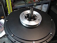
Kind of a queasy feeling drilling holes in a new motor fresh out of the box, but the drive gear had to be installed, and the hall and phase wires had to get clipped for the new set up. I was happy to see that the axle length and freewheel spacing were a perfect fit.
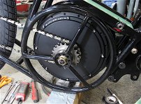
New Motor.jpg

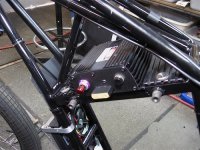
The Votol "clone" controller is getting wired up, and fits the frame nicely. This thing is cheap, but It looks like it's built well and is rated for 3Kw so I have high hopes, I'll be the guinee pig on this one.
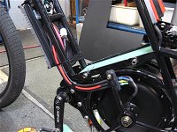
Phase wires.jpg

The phase wire route works out good, and there's plenty of room for the smaller connections between the tubes. Running 8 awg phase wires into the smaller motor wires is a bit sketch, but will have to do for now. I'll make some mounting straps for the controller once I see it work. Clipped most of the extra wires, but kept the cruise control, soft-start, 60v-72v, and three speed port.

Spent some time rewiring the fuse box for the new set-up, still have to install a push button voltage-equalizer - anti-spark.
 
OK, this is probably complete BS, but I've been thinking phase wires lately,.. the going through the motor axle thing. Why they don't just use bigger bearings on the left side for more room is beyond me, but that's what we have. :?

Instead of running three round wires parallel, I wondered if it would make any since to run them in layers. So I did a quick and dirty experiment with some braided flat wire to see what would happen.

Just a thought. Only needs to run 3" and then gets split off into separate wires.

Three Layer Braided phase wires.jpg

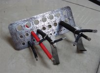
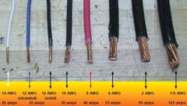
Three layers of 1/2" braided 50 amp is on the right, (= 8awg) ..150 amp continuous. 1/4" braided (= 10g) 30A on the left. 90A cont.
8g red silicon & 10g black single wires for reference.

Anyway, might be a little rough to bend into an elbow, but the outer heat shrink isn't really necessary since the motors internals aren't grounded. (The axle can maybe used as one phase wire too?)

.........

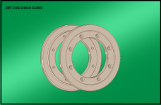
I have to make some chain guides for the cogs, so I whipped up a cad drawing of the front one,.. to be pop-riveted on the 20T cog. (..fun with colors)

20T Cog chainguide.png

The long single speed rear chain is going to be hard to keep put when it bounces around, especially with the offset chain line.
 
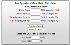
Also been using this nifty gear ratio calculator for mid-drives,.. scooters. Probably have your own version, but just enter motor RPM
and tire height, & play with cog numbers to get speed. (no wind & road resistance, so add a few mph.)

https://electricscooterparts.com/motorwheelgearratio.html

Mid drive gear ratio calculator.png
 
APL said:
OK, this is probably complete BS, but I've been thinking phase wires lately,.. the going through the motor axle thing. Why they don't just use bigger bearings on the left side for more room is beyond me, but that's what we have. :?

Instead of running three round wires parallel, I wondered if it would make any since to run them in layers. So I did a quick and dirty experiment with some braided flat wire to see what would happen.

Just a thought. Only needs to run 3" and then gets split off into separate wires.

Three Layer Braided phase wires.jpg

Three layers of 1/2" braided 50 amp is on the right, (= 8awg) ..150 amp continuous. 1/4" braided (= 10g) 30A on the left. 90A cont.
8g red silicon & 10g black single wires for reference.

Anyway, might be a little rough to bend into an elbow, but the outer heat shrink isn't really necessary since the motors internals aren't grounded. (The axle can maybe used as one phase wire too?)

.........

I have to make some chain guides for the cogs, so I whipped up a cad drawing of the front one,.. to be pop-riveted on the 20T cog. (..fun with colors)

20T Cog chainguide.png

The long single speed rear chain is going to be hard to keep put when it bounces around, especially with the offset chain line.
I really like this idea for the cable in principle.

Could you post some pics of equivalent copper cross sectional area bundles of 3 wires vs your concentric one?

This would be excellent from an EMC perspective. Not that you really care.

Any reason not to take it all the way to the controller? It would be nice and tidy.

I have a load of this braid. If it works out for you I'll give it a try.

Only issue I see is that it might have higher resistance since the strands are at 45 degrees so effectively 1.4x as long and thinner
 
Great! Maybe it has some merit,.. braid could go all the way for sure. Cross strands make less space and more resistance your right, I'm not sure if there's better quality braids. Thought that I saw some silver plated somewhere.

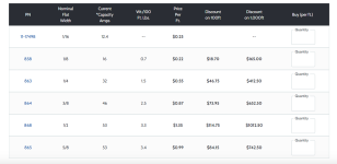
Braid chart is from Aircraft Spruce, and the wire pic is just an image grab.

tinned copper braid  amp capacity.png

Wire gauges comparison amps.jpg

When I looked around at charts, the amp values changed a little, but generally these are some values.
That's ampacity anyway, I'll have to do some work to get any cross sectional comparison info.
 
APL said:
OK, this is probably complete BS, but I've been thinking phase wires lately,.. the going through the motor axle thing. Why they don't just use bigger bearings on the left side for more room is beyond me, but that's what we have. :?
This has been proposed numerous times over the years. ;) IIRC me and John in CR talked about it in various posts a number of times; don't recall if he ever did the mod to his hubmonsters or not.

Some people have modified motors to do this; I had planned to do it on more than one motor type, but was never able to make new side covers for it.

Somewhere in my various posts about it there are some sketches that include just making a circular spacer to go on an existing axle, with holes for each phase wire plus a hall / sense / etc cable. This would be "glued" down to the axle (or keyed to it with a slot-key) to prevent rotation and wire damage.

A larger ID bearing would go over this for the rotor (motor side cover) to ride on; this would require significant modification of any existing side cover and probably easier to just make a new cover from scratch. For instance, a support ring for the new bearing's OD could be properly centered and bolted to the existing side cover, and the material of the cover that would interfere with the new phase/etc wire exits would be removed.


The primary problem with doing this on a hubmotor is it will interfere with ability to use bicycle freewheels or disc rotors, so for wheel-mounted hubmotors (unlike yours) it means losing one or the other if you were using them. So that's why you don't see them on common ebike motors. (that and manufacturers are cheap and very slow to adopt anything new that costs more but doesn't make any more money...)

FWIW, I think the Grin All Axle motor and the GMAC both do this, but they may be the only current commercial offerings.
 
Thanks amberwolf, manufacturers are $$ conscious and slow to adopt, is understandable. They probably don't want folks like us to
go pumping massive power through their products either. If it's rated 1500w, then that's what it is, get a bigger motor!
Also understandable.

But boys will be boys, so we're left with devious modifications. :wink: I would have bought a bigger QS motor, but the freewheel side is too short, axles too long and I need 4T windings. So mod it is,.. (and I like being devious). :lol:

The Leaf motor will be fine as is, the short 12awg wires will take quite a bit of power. Having just received it, I'll wait until there's several things to be done inside, but when the time comes, the phase wires will be high on the list.
 
Pounded out the cog guide on the lathe, I don't know what the final drive cog size will be until she gets on the road, so this might be a dry run. It pop-rivets to the cog, and slides over the adapters, just enough room on the Origin8 20T.

Motor guide.jpg

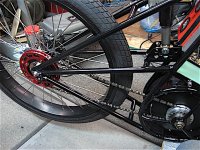
Finally got the 12G spokes in the rear wheel at long last! Sure is nice to have that out of the way, and I can start to put things back together there. The Sick Bike Parts 36T cog came pre-drilled for 104 BCD rings, so I mounted up a couple of chainring chain guards to help keep the chain on track.

Not sure how all this is going to work out yet, so we shall see.

Chain guides.jpg

I'll probably use a single speed der-hanger jockey wheel guide too,.. to take some chain tension off of the freewheel bearings, which tend to wear out fast otherwise.
 
Looks great!
But wouldn't something like 219 karting chain be a lot more durable at the power level the motor is capable of?
 
You're right, and bigger/better chain is in the plans for sure, but right now I'm sneaking up on it. I have lots of 3/32" cogs and chains, so I'm using that stuff up until I can figure out exactly what's needed for cog sizes, so I only buy once.

There's lots to learn about chains, I haven't paid too much attention because I've always ran 9spd & der, and that's kind of a no-brainer. Reading up on the excellent ES - Spinningmagnets chain thread at the moment; https://endless-sphere.com/forums/viewtopic.php?t=46630

A #219 chain system might be a little harder to convert to, but 1/8" is easy and I think probably strong enough, at least 'strong-er'. :?:
Thought I'd start with that first. I don't plan to beat the bike to death. Certainly a lot of stuff available with #219 though, so I'll look into it.

I built the frame for cassette and changed over to single speed. So wider chain is a bit of a problem at the moment, unless I get the torch out and re-arrange some tubes, but I think that's what really needs to happen.

Anyway, I started buying some 1/8" stuff,.. Izumi Super-tuff Track chain was pricey, but turned out to be a tad short, so now I need more. :roll:
 
I'm enjoying the build and the updates! Thanks for sharing. It my goal to build a tube style ebike in the future.
 
Thanks Mourningstar, hope some of it helps, do you plan to convert or build from scratch? Rear hub,.. mid drive?
Thanks for watching!
 
Not much to update, I looked into #219 chain parts, but front cogs are a bit of a problem. Space, and availability. Guess I'll wait until the need arises, or the next frame version. We'll see how things play out this summer.

I'm not too hot to rearrange this frame yet, because it's going to become a backup unit and all of the old parts will go back on it latter on. This frame is already getting outdated for what I'd like to do,.. so many changes to be made.

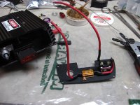
I did manage to get the voltage equalizer, or anti-spark switch started though. 6 amp momentary-on switch and 1K ohm 10W resistor.
Goes across the main switch. Probably overkill, but surge volts can destroy, and the info on these things is all over the board, so build it big and build it bad.

I plan to add an insulated solder post to the resistors left side, because the solder lugs on these things are weak and tend to crumble
if stressed, (yea, I broke one), and then there's a live wire kicking around.

Volt EQ.jpg
 
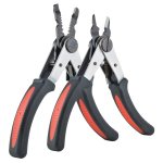
Detail of the wire strippers please? Don't think I've ever seen ones like that.
 
My favorite, got these from Radio Shack years ago, but they're still around on Amazon and other places. Usually called Mini-Switch
Grip, or just switch grip # 30589,.. Allied part # 30578 for around $15. Sold under many brand names.

Nice quality & handy for smaller stuff. (found this random source on Google Images) https://www.toolsource.com/crimperstripper-c-194_238_241/strip-grip-dual-jaw-precision-pliers-electricians-tool-p-126132.html

Switch Grip Wire Plier.jpg

Don't abuse the 'plier' tip though, or they'll snap. :oops:
 
A few more things,.. finished up the push button pre-charge on the secondary side with the 80 amp controller fuse. 60 amp on the primary side for system max, for now. (Looks like my old 8 track player.) :)

Controllers wired in and I have the CA and shunt hooked up, just have to program the CA shunt resistance to zero-in the watt meter.

80 Amp.jpg

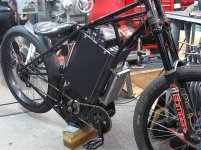
Made some controller mounts out of aluminum strap and heat shrinked them to tone it down. Better than the wire ties anyway. Thinking about maybe using quick release pins on it to make the hall connectors and back wires quick access.

Front cranks and chain are hooked up, and I'm working on making the side plates one piece and bonding on some foam to hold the battery snug. Still have to solder in the BMS connectors, I've been putting off, but other than that she's getting close to ready.

Had to ditch a rear chain guide,.. can't get the chain off otherwise.

V4 April.jpg

I could get a better picture if it wasn't snowing outside,.. future plans are for a new front wheel and some sweet floating rotors, but
I need to let the wallet to heal up.., so later on.
 
Thanks Eastwood, I've been looking over your super nice enduro build, .. love the color scheme! :wink:
Excellent work and massively beefy bike, I'd love to go with a motor and wheels like that. Maybe someday.

Kinda trying to stay with bicycle parts, but who knows how long that will last. Frame is still evolving and I'm already looking forward
to the next variation, chasing a look that I can't quite see.
 
Well it's been awhile, but I'm mostly going backwards on the Dread bike. Nothing very visible has been done,.. finished up the side
covers and bonded some foam inside, added some more plastic mud guards to the front and a short upper fender. New thread-less BB shell to clamp and tighten the front eccentric works nice.

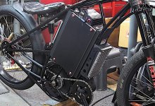
Made some fake carbon fiber 'look' side covers for the controller, still working on that...

Controller cover (3).jpg

Mostly stuck down in Chainsville, trying to get the rear chain to conform to my needs. The front aluminum chain guide I made for the motor sucks, (grabs & noisy), and the chain wants to bang around on everything and sound like a can of rocks.

So, I need to take it apart and redo the alum guide with some plastic or maybe just 3D print it. Also working on some chain silencer tubes to dampen the mid-chain section, don't know how that's going to end up, but sounds quieter so far. All works in progress.

Trying to install a DMR tensioner in back,.. really like the beefy stainless construction and deluxe jockey wheel, but it's made for vert-drops, so not fitting the best. Think if I remake the axle adjuster to come down and catch the DMR tab, I can get it to work out better. Nothing but trouble these days.

DMR  axle adj.jpg

Also scraped out the wallet 'one more time' and sprang for some new rotors, stepping up to a pair of 203mm front and rear for a little more stop power.

Still in the lower 40's outside and lots of rain, so not exactly ride'n weather yet anyways.
 
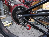
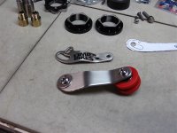
Decided to make my own arm out of some heavy stainless steel I had. Super sized it too. Works good, and one more thing off the list.

Strong arm.jpg

Another dread-worthy part.
 
Looks much better than the rim-brake-arm I used for a tensioner once on CrazyBike2. :)

Can't find a pic of it, but this from the mtbr forums gives the basic idea:
 

Attachments

  • napinacz[1].jpg
    napinacz[1].jpg
    114.2 KB · Views: 676
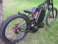
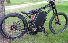
Finally rolled it out of the shop and onto some dirt! :thumb:

V4 22 5.jpg

Fixed the front chain guide with some plastic washers, and used some thick vinyl and double sided tape for the rest. Now it seems pretty quiet.

Had it working in the shop, but it crapped out on me when I rolled it out, so I still don't know yet. :roll:
Maybe tomorrow.

V4 5 22.jpg

Good news is that at least it's working.

Not right away though, I managed to get the 40 pin controller plug upside down at first, so I'm lucky it didn't fry something. :eek:
 
Back
Top