
You are using an out of date browser. It may not display this or other websites correctly.
You should upgrade or use an alternative browser.
You should upgrade or use an alternative browser.
Bafang M500/M600 thread
- Thread starter El_Topo
- Start date


casainho
10 GW
- Joined
- Feb 14, 2011
- Messages
- 6,047
That big chip is the W25Q256JV -- flash memory of 8 mega bytes.
Seeing this new pictures, now I think that small battery it to keep the Real Time Clock of the microcontroller STM32 running when this device is not powered. Usually the RTC is used to keep track of the seconds / minutes / hours and date. So, I wounder why it is needed for the system to keep the date... maybe there is a timeout limit to store the firmware, for security reasons??
Seeing this new pictures, now I think that small battery it to keep the Real Time Clock of the microcontroller STM32 running when this device is not powered. Usually the RTC is used to keep track of the seconds / minutes / hours and date. So, I wounder why it is needed for the system to keep the date... maybe there is a timeout limit to store the firmware, for security reasons??
casainho
10 GW
- Joined
- Feb 14, 2011
- Messages
- 6,047
1. I added to the repository the BESST hardware images
2. I added a Table of Contentes (automatically generated by an extension on Visual Code Studio)
We now have a BIG amount of technical data for M500/M600 motors!! This is really important as in Europe we are in war and the materials are now much more expensive as also the shipping cost from China. Also the shipping time from China increased - I am waiting for some parts since 1.5 months.
I made a mistake on my m600 motor purchase and got 43v setups instead of the 48v I ordered. 
Since so much time has passed (probably 9 months) and I already have all the batteries built for the two bikes I put together, I don’t have a way to get the 48v motors.
Is there a way to run the 48v batteries by running a Tvs diode inline somewhere? I remember this worked well on my ultra bike I had built running 15s.
If anyone can help, I’d be eternally grateful
casainho
10 GW
- Joined
- Feb 14, 2011
- Messages
- 6,047
Isn't there just a configuration to make the motor run with 48V or 52V battery??big4x4 said:I made a mistake on my m600 motor purchase and got 43v setups instead of the 48v I ordered.
Since so much time has passed (probably 9 months) and I already have all the batteries built for the two bikes I put together, I don’t have a way to get the 48v motors.
Is there a way to run the 48v batteries by running a Tvs diode inline somewhere? I remember this worked well on my ultra bike I had built running 15s.
If anyone can help, I’d be eternally grateful
Animalector
10 kW
I just flashed 48V firmware onto a 43V motor it worked just riding around on test.
I'll have to update later with more results when it gets ridden more.
I'll have to update later with more results when it gets ridden more.
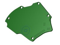
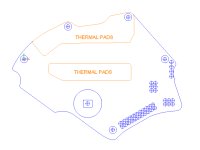
Not sure if this is of any use to anyone, but I had some time over lunch, so I digitized the controller board outline and key components in the layout. The mosfets obviously need to sit above the thermal pads on the cover and the magnetic sensor is relatively critical to have centered and properly offset above the magnet. Also I located the pin headers for convenience. Ultimately, my goal would be to get a VESC style controller in this format, so we'd have full control over the operating parameters. It's just a multi-horse race to see if this project ever comes to pass, we actually 'crack' the CAN code / firmware and get that functionality, Luna ultimately releases the V2 controller for retrofit, or something else entirely!
I'll add dxf files, though if someone takes a crack at this and those don't work we can possibly try some other way to communicate between CAD software!
I'll add dxf files, though if someone takes a crack at this and those don't work we can possibly try some other way to communicate between CAD software!
Attachments
casainho
10 GW
- Joined
- Feb 14, 2011
- Messages
- 6,047
The place for that files is on the repository - I suggest you to make a pull request. You can add a folder on inside hardware folder.4πr^2 said:Not sure if this is of any use to anyone, but I had some time over lunch, so I digitized the controller board outline and key components in the layout. The mosfets obviously need to sit above the thermal pads on the cover and the magnetic sensor is relatively critical to have centered and properly offset above the magnet. Also I located the pin headers for convenience. Ultimately, my goal would be to get a VESC style controller in this format, so we'd have full control over the operating parameters. It's just a multi-horse race to see if this project ever comes to pass, we actually 'crack' the CAN code / firmware and get that functionality, Luna ultimately releases the V2 controller for retrofit, or something else entirely!
I'll add dxf files, though if someone takes a crack at this and those don't work we can possibly try some other way to communicate between CAD software!
We are developing our EasyDIY motor controller and for what I can understand, to replicate the original board, the components need to be very tiny due to the limited space, and that implies that will be very hard to solder as DIY. But even if someone can DIY the board, due to so small components, it will be hard to and repair, because after assembling the board, it is always need to be tested and that small components will increase the probability of errors - basically this are components size the be assembled by machines. And the boards also to be tested by machines.
The only option I see is to build our motor controller and being able to increase the size of the original one, maybe make it thicker, to divide it 2 boards, one on top of the other. Expand to the outside but I do not know how much space is left due to the crank:

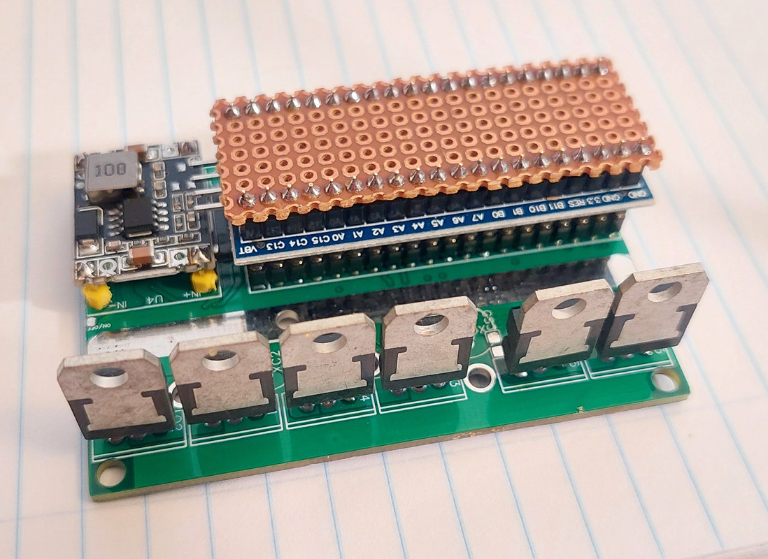
Here the example of our EasyDIY motor controller. I can say the area is of similar one as M500 motor controller, but the thickness is like 2.5x more:

Here more details (missing some components on this pictures) - due to good size components, they are easy to build or remove to solder. Also the DC-DCs for instance, are small boards, that can be easy tested outside before assembling as also easy to remove and replace for a new one in case of a fail.


Hello, I have a bicycle with a Bafang M500, 36V motor, it bothers me that at 35V the battery will limit the help to smaller W. I have an even older bicycle with a Bafang BBS02B 500W 36V motor. There I have the battery shutdown set to 32V. It does not limit the range and the battery does not matter.
Is such a modification possible for the M 500? Doesn't any other hardware on the M500 allow it? Now I use factory.
Is such a modification possible for the M 500? Doesn't any other hardware on the M500 allow it? Now I use factory.
casainho said:The place for that files is on the repository - I suggest you to make a pull request. You can add a folder on inside hardware folder.
...
Here more details (missing some components on this pictures) - due to good size components, they are easy to build or remove to solder. Also the DC-DCs for instance, are small boards, that can be easy tested outside before assembling as also easy to remove and replace for a new one in case of a fail....
I may try to give github another shot. Last time I guess I goofed something up with my 'request' - I'm certainly no github guru. If you want to copy the files there, feel free. I may be adding updates at some point later.
As far as the self build / self replacement of components, that is certainly one option. Though as you say, it would likely lead to some bulky / add-on box type board. My thought is that if the board is built robustly and reasonable limits are exercised in software/hardware, then it should not really be an item in need of constant repair. As an example I've probably put a million miles or more on various cars since the mid 80's and later. I don't recall ever having an ECU break down or need repair. So outside of a 'one in a million' failure of some component, the overall board should not really fail and could lend itself to quick assembly at a fab house.
casainho
10 GW
- Joined
- Feb 14, 2011
- Messages
- 6,047
I just received my motor and I connected a cable to the brake connectors, where CAN is also available. I connected the oscilloscope to find the CAN wires and was easy to find them as you can see the signals are typical CAN waveforms.
My next step is to connect the USB CAN cheap device and unlock the max speed, from 25km/h to the 60km/h.
I will also write an How to unlock the Bafang M500/600, using the cheap USB CAN adapter, and put focus on it on the main page. (Updating the notes CiDi already did).


My next step is to connect the USB CAN cheap device and unlock the max speed, from 25km/h to the 60km/h.
I will also write an How to unlock the Bafang M500/600, using the cheap USB CAN adapter, and put focus on it on the main page. (Updating the notes CiDi already did).
casainho
10 GW
- Joined
- Feb 14, 2011
- Messages
- 6,047
I mean repair in the case when you assembly by hand the board and made some mistake by accident. For instance, the DC-DCs are hard to debug when they are failing. Well, electronics are hardware to debug. Assembling by hand this boards with such small components, it is an high risk and just for a few users... :-(4πr^2 said:My thought is that if the board is built robustly and reasonable limits are exercised in software/hardware, then it should not really be an item in need of constant repair.
That way, I think the much better option is to invest the money instead on buying original motor controllers for using on developing the firmware - in the end, would be much easier for average user to open the motor and solder the needed 4 wires to flash the firmware.
But maybe, later in some months ahead, I will invest some time to explore the idea of using our EasyDIY ESC, divided in 2 boards.
for curiosity I test the NRF52840casainho said:@SUPERJC, if you move to the NRF52840, you can still drive any display, continue to have the Bluetooth communication with Garmin Edge, and, with added feature of changing the Garmin page directly from the same remote you use to change the assist level of your motor. Garmin page change uses ANT+ Controls profile. We already have this implemented. You can get the source code on the GitHub.
You can program the NRF52840 in C/C++ or Python!!
And very good that Garmin customized data field, I was not aware of such tool!!
My first impression it is less easy and slower to develop than ARDUINO ESP32 (BLE + WIFI)
The NRF only benefit is ANT+
If I need ANT+ I'm thinking of using the NRF only as ANT+ transmitter
The ARDUINO ESP32 community is bigger for help
CAN Protocol ESP32 –> YES WE CAN
https://www.instructables.com/CAN-Protocol-Yes-We-Can/

casainho
10 GW
- Joined
- Feb 14, 2011
- Messages
- 6,047
NRF also has Arduino or Python, so it is very easy to develop for. BUT, my plan is to not develop much, instead reuse the current display firmware, that was developed for be quick and fast to reuse/adapt to other devices.SUPERJC said:for curiosity I test the NRF52840casainho said:@SUPERJC, if you move to the NRF52840, you can still drive any display, continue to have the Bluetooth communication with Garmin Edge, and, with added feature of changing the Garmin page directly from the same remote you use to change the assist level of your motor. Garmin page change uses ANT+ Controls profile. We already have this implemented. You can get the source code on the GitHub.
You can program the NRF52840 in C/C++ or Python!!
And very good that Garmin customized data field, I was not aware of such tool!!
My first impression it is less easy and slower to develop than ARDUINO ESP32 (BLE + WIFI)
The NRF only benefit is ANT+
If I need ANT+ I'm thinking of using the NRF only as ANT+ transmitter
The ARDUINO ESP32 community is bigger for help
CAN Protocol ESP32 –> YES WE CAN
https://www.instructables.com/CAN-Protocol-Yes-We-Can/
The only missing part to have the display working for M500/M600 is to add the driver for MCP2515 CAN IC, and there are many libraries on github, C code, ready to be used for the MCP2515 CAN IC.
casainho
10 GW
- Joined
- Feb 14, 2011
- Messages
- 6,047
I just started looking at CAN drivers for the SPI CAN module, as I received the module today.
I am looking to this library in C: https://github.com/sledziu1/CanIC
I already worked with that SPI CAN module both with Arduino and Raspberry Pi, so I think it will be quick to have it working.
I am looking to this library in C: https://github.com/sledziu1/CanIC
I already worked with that SPI CAN module both with Arduino and Raspberry Pi, so I think it will be quick to have it working.
casainho
10 GW
- Joined
- Feb 14, 2011
- Messages
- 6,047
I am out of luck. I have with me 2 different USB CAN devices, the most cheap ones. I used a few hours to test both and I could not receive any CAN data from the motor although I see the data on the oscilloscope. I did follow the CiDi guide and other guides, it should be very simple to receive the motor CAN data, still I was not able to get it.
So my next step is to use the SPI CAN module on the display, it will work for sure.

So my next step is to use the SPI CAN module on the display, it will work for sure.


casainho
10 GW
- Joined
- Feb 14, 2011
- Messages
- 6,047
The idea is to reuse as much as possible on the hardware side and firmware side, from the well tested EasyDIY display TSDZ2 version.Hagbard said:Excellent!
Is the plan to accomodate the Nordic module inside the display case also, or are you thinking of locating that component inside the frame? There's plenty of space above the battery, and the more that's out of the way the better IMHO.
Reuse to help finish this project as soon as possible. So, the only additional thing needed for the Bafang M500/M600 version is the CAN module, and that will probably increase the display thickness by 7mm.
The EasyDIY display will have about 33% less volume than the DP C24x display:
- Bafang DP C24x display: 58mm * 46mm * 25mm = 67 cm3
- EasyDIY display Bafang version: 47mm * 37mm * (19 + 7)mm = 45 cm3
- EasyDIY display TSDZ2 version: 47mm * 37mm * 19mm = 33 cm3
casainho
10 GW
- Joined
- Feb 14, 2011
- Messages
- 6,047
The very begin: I have the full hardware display ready (added the CAN module) and also have the library to control the CAN module, already building on the firmware. I will work on this during the weekend (but still I will be with family as also I will run on a trail run event).
My Dengfu E10 frame may arrive next week

My Dengfu E10 frame may arrive next week
Waynemarlow
10 kW
On another forum one of the guys is trying to build a smaller keypad, he has mentioned about having to change the Baud rate to 250KBS before the cheapo CAN readers would work. Is this something to consider ?casainho said:I am out of luck. I have with me 2 different USB CAN devices, the most cheap ones. I used a few hours to test both and I could not receive any CAN data from the motor although I see the data on the oscilloscope. I did follow the CiDi guide and other guides, it should be very simple to receive the motor CAN data, still I was not able to get it.
casainho
10 GW
- Joined
- Feb 14, 2011
- Messages
- 6,047
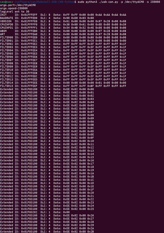
Thanks, I tested again and it works!!Waynemarlow said:On another forum one of the guys is trying to build a smaller keypad, he has mentioned about having to change the Baud rate to 250KBS before the cheapo CAN readers would work. Is this something to consider ?casainho said:I am out of luck. I have with me 2 different USB CAN devices, the most cheap ones. I used a few hours to test both and I could not receive any CAN data from the motor although I see the data on the oscilloscope. I did follow the CiDi guide and other guides, it should be very simple to receive the motor CAN data, still I was not able to get it.
It is so easy!! just wire the USB CAN adapter CAN_H and CAN_L wires to the HIGO-B6-F connector, and connect it to the brake connector on the motor. Once you turn on the display, the motor will start sending the data to the CAN. You can also send data to the motor, for instance to change the max speed and wheel diameter: https://github.com/OpenSourceEBike/Bafang_M500_M600/tree/main/CANBUS
HIGO-B6-F connector is not that much expensive:

USB CAN adapter on Aliexpress:

Similar threads
- Replies
- 0
- Views
- 428
- Replies
- 0
- Views
- 1,095
- Replies
- 3
- Views
- 456
- Replies
- 16
- Views
- 3,564
- Replies
- 1
- Views
- 425