BMS question

Geoffers

1 W
Joined
Oct 10, 2023
Messages
57
Location
Devon
Hi all,

First post on here so be gentle please!
Not strictly a ev question either but....
I'm building a off grid mobile robotic milking system.
I had planned to use eve 280aH cells(16 of) to run everything through a set of 3 inverters (3 phase system). For that I had bought a 300A Daly BMS.

I've been let down on the eve cells a couple times so have gone mad and should have 8 X 4s Hyundai ev batteries on the way.

This will give me 2 banks of 16 cells. Should I buy another BMS or would it be better to put link wires between the cells in each pack so the BMS sees one bank of 16 cells? In effect making up a 2p16s battery out of the 8 packs?

I'll check the cells are all around the same voltage before I connect up!

I promise to make a electric crosser 👍

Thanks Geoff
 
Each inverter produces one phase, neutrals are all linked.

The more I think about the more I think I should put link wires in, as long as the cells are fairly well matched and in good order there shouldn't be any current flowing in the links?

The setup I built before for our house used seplos 16s BMS and they're are designed to be 'stacked' in parallel with the first one controlling what the the rest do when they are charging or discharging

Cheers Geoff
 
Sorry yes, 415v 3 phase ac for the robots and associated gear
It's built into a container, plan is for about 15kw solar on top , has a 3 phase diesel generator for back up.
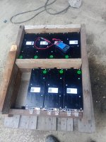
8 X Hyundai 4s 2.385kwh batteries
Cheers Geoff
 
I'm curious what kind of converters are these where each phase is split up in a separate converter?

But you should probably draw a diagram of things you are trying to do. Word descriptions of electrical systems doesn't really work.
 
Quite a few do it, I've used victron and now am trying a brand called growatt, I've got a baby system really, 3x5kw for a 15kw 3 phase system, you can use up to 12 I believe.
I'll draw out a diagram later

Cheers Geoff
 
Sounds like I misunderstood. You have 3 separate inverters providing 3 separate outputs of 3 phase AC power.
 
Each one drives one phase, neutrals all joined and they are linked with a data cable so they stay 120 degrees from each other
 
IMG_20231016_092712_623.jpg

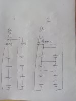
Here is my hi tech diagram!
I've drawn 4 cells a bank as I couldn't be bothered to do 16. The BMS sense wires are ignored as it would look a mess!

Which option is the best,

1) has 2 batteries and 2 BMS, this is how alot of off grid batteries are done with the BMS talking to each other. (At the moment the seplos BMS seems tricky to get hold of)

2) one BMS and each pair of cells linked so the BMS senses the voltage of 2 cells in parallel, this is my preferred method as I already have one 300A BMS.

Is there any reason not to use the second method? (Assuming the cells are all equal and in balance before I start)

My cells are second hand from a 2023 Hyundai so shouldn't have done much I hope.

Cheers Geoff
 
I have made about 10 different battery packs like your 2nd method with no issues. I even used 26AWG wire, I wouldn't use such thin wire with used B grade cells though.

Are those Hyundai cells Lifepo4? Because if not then 16S is too high of a voltage for your 48V inverter, in that case you should go with 14S
unless you plan on not charging over 3.7V per cell, which doesn't make sense for Li-ion type chemistries.
 
Thanks, funny enough I've just been reading the inverter instructions and realized my mistake! Too late now they are in a van somewhere,I'll have a spare battery pack is suppose.

Would you try and top balance the cells? Until I get them I don't know if they are welded etc, any value in balancing the packs of 4 cells.

Cheers Geoff
 
The way I do the balancing depends on the cells.

If all of the packs came from the same car I think you won't need more than the 60-100mA of balancing that most BMS provide.

I've got some Samsung SDI packs that have been running for over a year without any balancing.

My recommendation is not to use a active balancer, unless you've got some really bad cells.
And even if the cells drift slightly towards the end of discharge, it's better to not balance them at the bottom because when charging they get unbalanced again at the top.
 
Thanks, yes I think all the cells came from the same car, they should be here tomorrow 😄
The Daly BMS has passive balance as far as I can tell.
I'll get the meter on them as soon as they arrive and see what's what!
 
Ok, now I'm unsure!

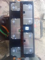
IMG_20231017_152028_959.jpg
I was going to ask the best way to split the busbar (other than f"£&ing carefully!)
The seller carefully avoid my question about the nominal voltage on these batteries they are sat at 3.54v which I realise means very little.


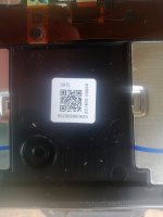
IMG_20231017_152036_993.jpg
This is inside the case,it seems catl manufacture lifepo4 batteries, I don't want to be rash and cut anything I don't need to. Is the best plan to pretend they are lifepo4, charge the to 3.65v/cell and see if they're still taking current? Or are they definitely lithium ion?
 
You can easily cut and then bend the aluminum upwards and bolt some wires to it, I've done something similar before.
 
Thanks, I scribed them and then cut them with the end of a hacksaw blade, they bent surprisingly easy 😄
 
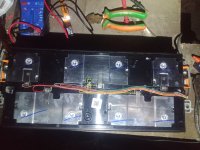
Just connecting this all up now, I ended up buying some d sub cables, cutting them in half and soldering to the nickel strips on the cellsIMG_20231116_171319_743.jpg

I've soldered wire to the temperature sensors so they are on the dsub connector, I've made up a connector box that parallels the batteries and joins to the BMS cables.

Which brings another question! I bought the BMS (which is a Daly 16s 300A) for the li po4 batteries I was intending on using, I've now ended up using li ion at 14s.
The BMS states its for li po4 doesn't say anything about li ion. I was hoping I could just alter the settings to suit. With 14s connected up, nothing happens, voltage each cell is 3.5v so in range for li po4.

I'm going to contact Daly, but I guess it won't work with 14s so is just trying to protect battery.

Any suggestions for a BMS, I could do with a contactor one really as I'd like to be able to charge at around 300A

Thanks Geoff
 
Thanks, I'm unsure if I can use it too, been reading up on Daly and it seems a minefield!
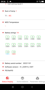
Managed to get it connected to Bluetooth this morning, changed parameters to li ion, changed a few voltage settings set as 14s, thought should be good to go.
Screenshot_20231121-093652.png

Cell 13 and 14 voltages read wrong? More concerning is the range of voltages 3.8-3.5???
My multimeter makes them all 3.53
If I change settings back to 16 s 15 and 16 also read 5v which suggests to me 14 is open circuit as 15 and 16 are?

Thanks Geoff
 
Ok answer my own question (sort of!) If I tie the last two series/balance wires to v+ the voltage readings look much better and it starts up.

I'm reluctant to change the BMS if it will work ok like this? Anyone foresee issues if it starts to balance? Presumably if it's set as 14s it will only try and balance 14s :oop::oop:
 
How comforting 😀
Have got 3 phase now, nothing connected to it and have drawn a huge 250w through the daly
 
Back
Top