BMS question

Your right it's a greedy sod ! 1.4A @ 13v 18.2w!!!
You're reporting that this is the idle draw to keep the contactor closed? You're right, that's fine for an ebike or emoto, on for 15-60 minute rides, but that's too much for 24/7 small DIY powerwall usage. Hopefully swapping out the contactor as you're planning would improve that.
 
Yes but maybe taken with a pinch of salt, the voltage will be accurate but I did measure the current with a cheap DC clamp amp so maybe a bit out.
I had a feeling it might draw a lot, the whole BMS wasn't much more than the contactor I've ordered !
 
A solid state relay is not different than a MOSFET BMS. I wouldn't dare to rely on a garbage SSR from AliExpress. A good quality one from a brand name will cost more than the BMS and will add no benefits.
 
Someone did manage to find an IGBT based BMS on this forum once instead of a MOSFET based one. So that might be a third option other than a physical contactor. They can handle more current/voltage than a MOSFET.
 
Last edited:
A solid state relay is not different than a MOSFET BMS.

It is different because you can pick whatever ampacity you want, not just what the BMS supports.

If you distrust inexpensive Chinese semiconductors, I have some possibly alarming news for you....
 
It is different because you can pick whatever ampacity you want, not just what the BMS supports.

If you distrust inexpensive Chinese semiconductors, I have some possibly alarming news for you....
Chalo, this is the first I've heard of DC SSRs with that kind of amperage rating. Do you think it would be applicable to use a big SSR like that in place of a standard contactor in a larger DIY EV? What are the downsides, why aren't they being used more often?

Edit: LOL, when I first clicked on your link, I quickly read through the item and basically read that it was a 500A 75v SSR for $7.02. Then i see that $7.02 is the price for the aluminum heat sink, and the actual relays are $94 and $145. Nevermind, contactors in that rating are way cheaper, so that basically answers my question.

Not to say there is no use for a high-current SSR, just not what I had imagined.
 
Not to say there is no use for a high-current SSR, just not what I had imagined.

I think the main benefit is eliminating the spark when juicing a controller full of chonky capacitors. Plus less wear, consistent resistance, etc. One drawback is more waste heat to dump if you're really giving it the beans.

I didn't go price shopping, just googled "500A SSR" and grabbed a link for an example.
 
How much current can I push into these batteries CATL li ion 190aH

Specs from a randomly chosen seller page for these (safer to check the manufacturer site if you can find it). copy/pasted below, show that they are intended for 0.2C charge rate, which is 0.2 x 190Ah = 38A, for a 1P pack (regardless of number in series, just one in parallel). Same or very similar specs on the few I checked of the many that come up.

They have a max rate of 1C, or 190A; those kinds of specs usually mean for short bursts (like if using them for regen braking, etc) a few seconds at a time. You'd need the manufacturer spec sheet to be sure but it is safer to assume that than to assume it's a constant ability. ;)

Multiply that 38A by however many parallel cells you have to get the charge current you could use per pack.

If you have two independent 1P packs (each with their own charger / BMS) then each one can be charged at 38A.

If you have a single 2P pack with a single charger and BMS, then it can be cahrged at 2x 38A = 76A.

They have the same discharge ratings, so 38A is the normal current you can draw from them, for 1P, or 76A for 2P.


Copy/pasted specs:

Note: The Lifepo4 CATL 3.7V 190Ah battery are original brand new cell with clear QR code. For easy assemble, we will weld M6 studs on the cell. Each battery will send 1 pcs copper busbar and 2 pcs nuts. The price to European countries are include custom clearance and tax.
Battery Specification
Model: ND-3.7V 190Ah
Nominal voltage: 3.7V
Standard capacity: 190Ah
Size: 148*80*106mm (Not included the studs)
Weight: About 2.8Kg
Charge voltage: 4.3V
Discharge cut-off voltage: 2.8V
AC internal resistance: ≤0.5m Ω
Standard charge current: 0.2C
Max. charge current: 1C
Standard discharge current: 0.2C
Max Continuous discharge current: 1C
Operating Temperature
Charge: 0℃~50℃
Discharge: -20℃~55℃
 
Chalo, this is the first I've heard of DC SSRs with that kind of amperage rating. Do you think it would be applicable to use a big SSR like that in place of a standard contactor in a larger DIY EV? What are the downsides, why aren't they being used more often?
SSRs are usually made from FETs, or from Triacs or SCRs.

So in addition to the RDSon resistance of the devices (which generate heat from current thru them), they can have the same common failure modes (stuck on) and vulnerabilites that a FET based BMS does (or any other FET-based switch), So if the device fails, the connection may not be able to be broken, and the protection the device is there to provide unavailable.
 
Specs from a randomly chosen seller page for these (safer to check the manufacturer site if you can find it). copy/pasted below, show that they are intended for 0.2C charge rate, which is 0.2 x 190Ah = 38A, for a 1P pack (regardless of number in series, just one in parallel). Same or very similar specs on the few I checked of the many that come up.

They have a max rate of 1C, or 190A; those kinds of specs usually mean for short bursts (like if using them for regen braking, etc) a few seconds at a time. You'd need the manufacturer spec sheet to be sure but it is safer to assume that than to assume it's a constant ability. ;)

Multiply that 38A by however many parallel cells you have to get the charge current you could use per pack.

If you have two independent 1P packs (each with their own charger / BMS) then each one can be charged at 38A.

If you have a single 2P pack with a single charger and BMS, then it can be cahrged at 2x 38A = 76A.

They have the same discharge ratings, so 38A is the normal current you can draw from them, for 1P, or 76A for 2P.


Copy/pasted specs:

Note: The Lifepo4 CATL 3.7V 190Ah battery are original brand new cell with clear QR code. For easy assemble, we will weld M6 studs on the cell. Each battery will send 1 pcs copper busbar and 2 pcs nuts. The price to European countries are include custom clearance and tax.
Battery Specification
Model: ND-3.7V 190Ah
Nominal voltage: 3.7V
Standard capacity: 190Ah
Size: 148*80*106mm (Not included the studs)
Weight: About 2.8Kg
Charge voltage: 4.3V
Discharge cut-off voltage: 2.8V
AC internal resistance: ≤0.5m Ω
Standard charge current: 0.2C
Max. charge current: 1C
Standard discharge current: 0.2C
Max Continuous discharge current: 1C
Operating Temperature
Charge: 0℃~50℃
Discharge: -20℃~55℃
Thanks, I didn't add enough detail! The batteries are from a 2023 Hyundai, I bought them second hand and understood they were nvm not lifepo4? That seems a funny voltage for lifepo4?

I'll do a bit more digging!

Cheers Geoff
 
I think the main benefit is eliminating the spark when juicing a controller full of chonky capacitors. Plus less wear, consistent resistance, etc. One drawback is more waste heat to dump if you're really giving it the beans.

I didn't go price shopping, just googled "500A SSR" and grabbed a link for an example.
I had considered it, yes but the contactor seemed a better option for me, once my setup is going it will be running 24/7 so the contactor won't be going on and off very often and I'll have a pre charge setup to avoid arcing on power up.

Does make me think I should have a test schedule for the contactor maybe once a week or something make sure it still breaks.

I'll regularly be pulling reasonably large loads, 3 phase compressor, hydraulic pump, vac pumps, then pushing a fair bit back in when the sun shines 😎
 
Just working things out here for a little system to monitor the battery temperature, seems anything over 55*C is bad for discharge 50*C for charging?
Which rounds me down to making something that will throw the contactor at 50*C as it won't know if it's charging or discharging and 0*C at the other end?
I can't see the cabinet it's all in ever dropping below 0*C
Thanks Geoff
That sounds like a good plan, though I personally would have a high temp cutoff of 40-45 degrees. That's up to you and your battery specs though.

Also, if you haven't ordered a replacement contactor yet, BatteryHookup is selling good ones, salvaged, for $12.50 now. I tested them myself, I think they only use 3-5W to keep the contacts closed.

Cheers, that is the one I've ordered!
I'm in the UK and paid £30 for a new one, should get it next week!

I'd rather go cautious so will make my monitor trip at 45*C !
 
Thanks, I didn't add enough detail! The batteries are from a 2023 Hyundai, I bought them second hand and understood they were nvm not lifepo4?

A quick google on 2023 Hyundai battery finds a bunch of different things; which specific vehicle was it from?

Knowing that you could look up specs on that vehicle, including how many series and parallel modules are used, and what current draw the vehicle places on them. Then knowing those, you can divide the current draw by the number of parallel modules, which tells you the current a single module can supply.

That then gives you a safe limit to stick to.


That seems a funny voltage for lifepo4?
Yeah, it's not the right voltage range for LFP; ads and sales pages like those are often full of contradictions and errors. That's why I always recommend finding the manufacturer datasheets for cells and when they're not available then just avoiding those manufacturers / cells.

Plus, there are plenty of places out htere that sell things claiming them to be one thing when they are not, sometimes they are "clones" of the thing and are similar (but almost always lower quality), sometimes they have very little to do with the thing they claim to be. Until you've spent the money and tested those kinds of things (to destruction usually) you can't know what they really are (or capable of). :(
 
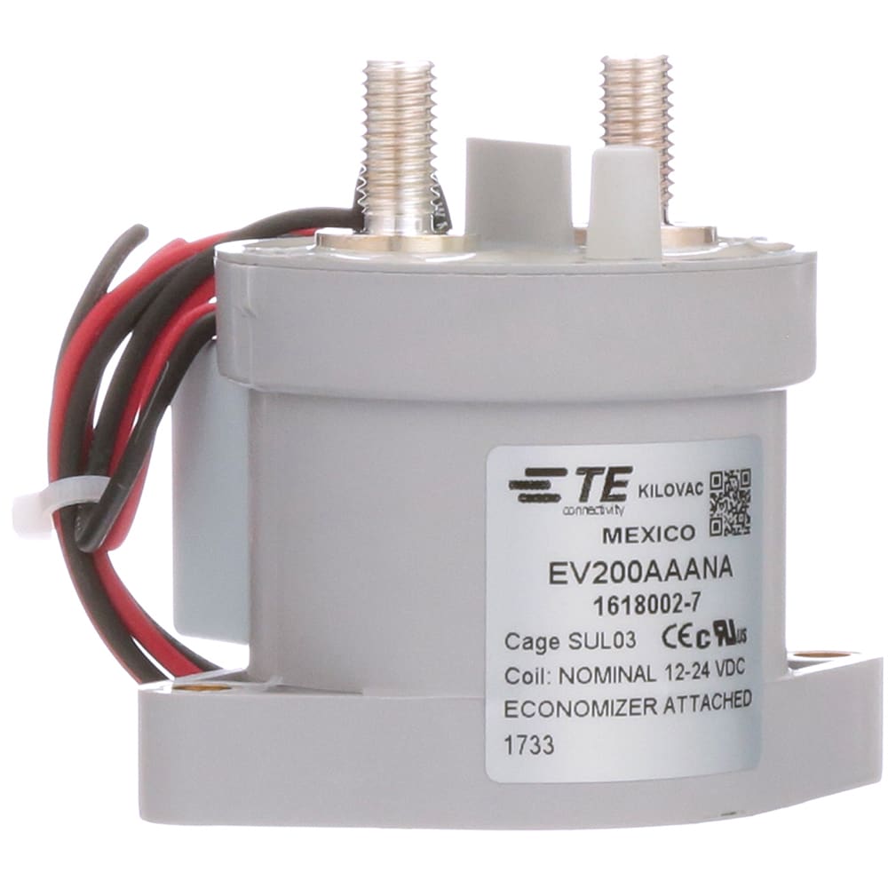
Contactor has arrived, quick bench test, it draws 170mA@ 15v so a whole 2.55w to hold it!
About 1.5A peak to pull it closed.
Compared to the one on the BMS that was around 15w?!
Nearly finished a quick and dirty pic based temperature monitor so hopefully should be up and running this week.
 
Contactor has arrived, quick bench test, it draws 170mA@ 15v so a whole 2.55w to hold it!
About 1.5A peak to pull it closed.
Compared to the one on the BMS that was around 15w?!
Nearly finished a quick and dirty pic based temperature monitor so hopefully should be up and running this week.
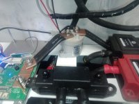
Do you have a 3d printer? I just had to draw up a cover for that contactor, in case you wanted the file.
 
Thanks I haven't but a friend has! I'll fit it all together this week and see if it looks like it should have a cover on it, I'm not quite sure where it will fit yet?

Cheers Geoff
 
IMG_20240214_134454_336.jpg
Takes me ages to do anything! @harrisonpatm
Would your printed cover fit on there or are my busbars in the way?
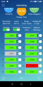
I'm just charging these up for the first time and cell 12 runs ahead a bit on voltage.
Screenshot_20240214-160512.png
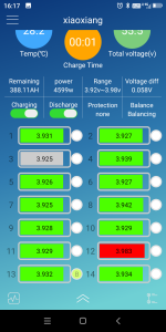
I've dropped the current a bit now and it's a bit better
Screenshot_20240214-161752.png

Is this a problem? The batteries have been sat a little while, as it was at the higher current I think the BMS might have turned off charging as cell 12 would have gone over the shut down voltage?
 
I'm just charging these up for the first time and cell 12 runs ahead a bit on voltage.
I've dropped the current a bit now and it's a bit better


Is this a problem? The batteries have been sat a little while, as it was at the higher current I think the BMS might have turned off charging as cell 12 would have gone over the shut down voltage?
This means that your cells are not identical in characteristics, such as internal resistance and capacity. This means that they will never perform identically, so those with higher Ri will sag more in voltage under load, and rise more in voltage under charge, and their probably lower capacity means they will always empty before the others. The sag in voltage under load means that since they will get lower in voltage first, they'll also cause more problems with early shutdowns during a ride as the sag drops below BMS LVC before actually being empty.

This problem will grow worse with time and usage, so if it's not much of a problem now, eventually it will be (how long that will take, we can't know until it happens since the reasons for these problems vary inside the cells).


The best way to "fix" such a problem (and prevent it) is to use only matched cells, that are identical in characteristics. This is hard to do with cells from most sources, new or not. The most certain way is to find used large-EV modules using large-format high capacity cells (vs ones built from lots of little cells), since typically these will be matched at the battery factory for these packs, so that the packs perform best for longest and give them as few warranty issues as possible. Places that scrap EVs, or sell such packs (batteryhookup, etc) often have these for sale.

If you don't have testing equipment for the various characteristics, a fairly simple test to see if they're matched is just to check their voltages--if they're all the same voltage within the pack or module when received, then just bulk charge them up to full at normal charging current for those specific cells, monitoring cell voltages the entire time manually, and if they all stay equal the entire time, all the way thru full, they're probably all matched in characteristics. A further test is to then discharge to empty (at normal discharge rates for those cells) and if they stay equal all the way down then they are matched. Any that become different under any of these conditions are not matched to the others and should be removed from the set (kept as spares for later if needed, perhaps).
 
Thanks,
These are fairly new 2023 Hyundai batteries, they are spot on when idle.
Just having come away from it for a bit and had a think, I've got a jbd BMS think it goes up to 21s, you have to join the spare inputs, I've done this at a junction box I made up so I wouldn't mind betting cell 12 has 6 or 7 wires running to it's input from the box.
I might try joining at the BMS and running one wire to the junction?
 
These are fairly new 2023 Hyundai batteries, they are spot on when idle.
When idle doesn't mean much as far as characteristics go. it just means they're all the same voltage, which by itself doesn't tell you anything.

It's when current is flowing in or out that you can see the difference in resistances as that creates differences in voltage.

Just having come away from it for a bit and had a think, I've got a jbd BMS think it goes up to 21s, you have to join the spare inputs, I've done this at a junction box I made up so I wouldn't mind betting cell 12 has 6 or 7 wires running to it's input from the box.
I might try joining at the BMS and running one wire to the junction?
Shouldn't make a difference to this particular issue.

If you see a difference in voltage while current is flowing thru the *cell stack*, then that's a difference in actual cell resistance.

Since you not only see that difference happening, but it lessens when you lower the current flowing thru the cell stack, that shows you the cell resistance difference fairly directly.


If you were seeing a difference in voltage change during balancing with no cell stack current flowing, it would indicate a wire resistance difference from the BMS to the cells involved.
 
Back
Top