Boston-Power Swing 5300 Li-ion cell test

Well there is one more thing on the BPs compared to 18650's on size. I would have to measure ...there may be an equaling out of size compared to two 18650s if you use plastic holders. Why? One plastic holder compared to two for the 18650's. At any rate ...like I said previously, the only issue to me is if you have a circumstance like building a triangle pack where you have a particular space that one 18650 fits in ...the BP will not go there. Of course there still may be ways to make them work in that situation. I just haven't tried it.

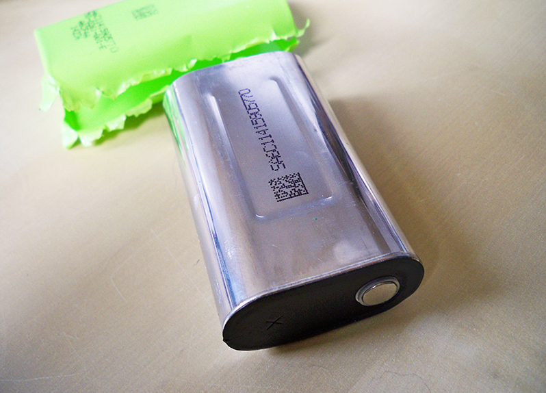
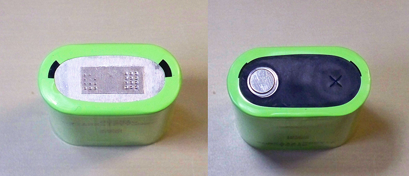
I feel the aluminum casing helps with heat dissipation ...why do you think heat sinks are made of aluminum? And I have no problems at all spot welding these ....or soldering them for that matter. Because Boston Power provided that weld tab.

I am glad we are having this discussion ...and I really like hearing all the critique. Thanks! Richard
 
Hillhater said:
Cycle life is a major factor in a true full cost comparason.
A cell that has 2-3 times the cycle life , is effectively half or one third the cost !
......unless you are using them in a “one shot” device like a missile ! :lol:

I had to laugh! Yes...exactly my use case...on a missile...ok...a street missile and not 1 shot. Where I would use these cells is on this scooter at 131v and I expect something like 120mph top speed on a 75cc sized moped. The motor is a 6 phase hubmonster...should be pulling something north of 30kw.

Taobao%20scooter%202.jpg


Shunt said:
I would think that large aluminum case is a pretty big deal too , since it dissipates heat to the outside of the cell much faster than a steel case would . If they weren't tabbed , I wouldn't even bother fooling with trying to weld one together , but since they are factory tabbed with nickel, it's a non issue .

Aluminum? Didn't know that and that will help, if the cells are not packed together and have a way to transfer the heat away from themselves, that could be useful.

Something I've wanted to mess with is copper or aluminum between cells to pull off heat. It could be done with copper capillary tubing or just solid metal. In either case, have a water manifold underneath to a radiator.

Tabbed? Well yes...it's an aluminum shell. Getting nickel to spot weld to aluminum will be very difficult. The little bit of nickel strip on the bottom of the cell is ultrasonic welded to the aluminum shell. Most folks can't afford the $4000 for a cheap ultrasonic welder! Is that positive post "button" heat tolerant? Typical 18650 cells can be directly soldered to as well, but you are getting awfully close the cells seal and getting it too hot will make the cell leak...and that IS BAD.
 
ElectricGod said:
Hillhater said:
Cycle life is a major factor in a true full cost comparason.
A cell that has 2-3 times the cycle life , is effectively half or one third the cost !
......unless you are using them in a “one shot” device like a missile ! :lol:

I had to laugh! Yes...exactly my use case...on a missile...ok...a street missile and not 1 shot. Where I would use these cells is on this scooter at 131v and I expect something like 120mph top speed on a 75cc sized moped. The motor is a 6 phase hubmonster...should be pulling something north of 30kw.

Taobao%20scooter%202.jpg


Shunt said:
I would think that large aluminum case is a pretty big deal too , since it dissipates heat to the outside of the cell much faster than a steel case would . If they weren't tabbed , I wouldn't even bother fooling with trying to weld one together , but since they are factory tabbed with nickel, it's a non issue .

Aluminum? Didn't know that and that will help, if the cells are not packed together and have a way to transfer the heat away from themselves, that could be useful.

Something I've wanted to mess with is copper or aluminum between cells to pull off heat. It could be done with copper capillary tubing or just solid metal. In either case, have a water manifold underneath to a radiator.

Tabbed? Well yes...it's an aluminum shell. Getting nickel to spot weld to aluminum will be very difficult. The little bit of nickel strip on the bottom of the cell is ultrasonic welded to the aluminum shell. Most folks can't afford the $4000 for a cheap ultrasonic welder! Is that positive post "button" heat tolerant? Typical 18650 cells can be directly soldered to as well, but you are getting awfully close the cells seal and getting it too hot will make the cell leak...and that IS BAD.

Yeh that tab they welded on the postive end of the can removes the problem you would have with spot welding. I believe the negative button is nickel plated steel, so no problem there. As far as the heatsink, if you had the space, a block of aluminum with a coiled up copper tube at the end of each parallel group to serve as a radiator would be cool. It would have to be isolated and spaced carefully though since it would be positively charged.
 
Shunt said:
ElectricGod said:
Tabbed? Well yes...it's an aluminum shell. Getting nickel to spot weld to aluminum will be very difficult. The little bit of nickel strip on the bottom of the cell is ultrasonic welded to the aluminum shell. Most folks can't afford the $4000 for a cheap ultrasonic welder! Is that positive post "button" heat tolerant? Typical 18650 cells can be directly soldered to as well, but you are getting awfully close the cells seal and getting it too hot will make the cell leak...and that IS BAD.

Yeh that tab they welded on the postive end of the can removes the problem you would have with spot welding. I believe the negative button is nickel plated steel, so no problem there. As far as the heatsink, if you had the space, a block of aluminum with a coiled up copper tube at the end of each parallel group to serve as a radiator would be cool. It would have to be isolated and spaced carefully though since it would be positively charged.

I have a spot welder..not a problem to weld, but why bother if you can solder?
 
ElectricGod said:
Shunt said:
ElectricGod said:
Tabbed? Well yes...it's an aluminum shell. Getting nickel to spot weld to aluminum will be very difficult. The little bit of nickel strip on the bottom of the cell is ultrasonic welded to the aluminum shell. Most folks can't afford the $4000 for a cheap ultrasonic welder! Is that positive post "button" heat tolerant? Typical 18650 cells can be directly soldered to as well, but you are getting awfully close the cells seal and getting it too hot will make the cell leak...and that IS BAD.

Yeh that tab they welded on the postive end of the can removes the problem you would have with spot welding. I believe the negative button is nickel plated steel, so no problem there. As far as the heatsink, if you had the space, a block of aluminum with a coiled up copper tube at the end of each parallel group to serve as a radiator would be cool. It would have to be isolated and spaced carefully though since it would be positively charged.

I have a spot welder..not a problem to weld, but why bother if you can solder?

I'm not knowledgeable enough to temp that fate. Supposedly lifting the tab up with a razor blade on the + end and soldering it isn't a problem because it's not in direct contact there , but Im not sure about that negative end. It's basically the same as an 18650 there, based on my ignorant assumption by looking at it .
 
Yes the negative end is just like soldering any 18650. And yes soldering them by lifting up that weld tab also is not a big deal. As I stated before spot welding with something like the Kweld is a breeze. So no real issues in creating a pack with these because of the aluminum case. Another anecdote is that there actually is a "vent side" on the Boston Power batteries which is supposed to help with heat dissipation.
 
Soldering to the negative end on an 18650 is not what bothers me at all. Same for the BP cells and it has a nickel strip on it so that's not going to transfer heat anything like soldering direct to the steel can on an 18650 would. It's the positive pole.

This is the top of a Samsung 18650. Heat from that tiny button cap transfers down the 3 "legs" into the seal around the edges of the cap. Too much heat and the seal melts. Bye bye cell! If I solder to the tops of these BP cells, I absolutely want to to avoid this as well! If they have a solder tab, the nickel wont transfer heat into the cell top very fast so soldering is doable.

P1040327.jpg


Looking at this image from page 1, I don't see a solder tab of any kind here. That's just the top of the cell. I'd say soldering to this is a bad idea, but I can't see under the black plastic cover either. If the button top is 2-5cm away from the actual top of the cell, that's plenty for me to solder and not transfer heat and melt seals. If that button is the actual top of the cell, soldering to it is asking for seal failures. I was hoping to find somebody who did a cell tear down so I could see under that black cover, but nada. Anybody know what's under that black plastic cover?

100_9625.jpg


If I understand "Vent side" properly it's the dented in section on the BP cell side. It allows the cell to bulge outwards. I guess these Phylion cells also have a "vent side" too if that's the case. The flat sides bulge outwards by about 1/8". As you can imagine, these cells are no longer useful.

P1040328.jpg
 
ElectricGod said:
Soldering to the negative end on an 18650 is not what bothers me at all. Same for the BP cells and it has a nickel strip on it so that's not going to transfer heat anything like soldering direct to the steel can on an 18650 would. It's the positive pole.

This is the top of a Samsung 18650. Heat from that tiny button cap transfers down the 3 "legs" into the seal around the edges of the cap. Too much heat and the seal melts. Bye bye cell! If I solder to the tops of these BP cells, I absolutely want to to avoid this as well! If they have a solder tab, the nickel wont transfer heat into the cell top very fast so soldering is doable.

P1040327.jpg


Looking at this image from page 1, I don't see a solder tab of any kind here. That's just the top of the cell. I'd say soldering to this is a bad idea, but I can't see under the black plastic cover either. If the button top is 2-5cm away from the actual top of the cell, that's plenty for me to solder and not transfer heat and melt seals. If that button is the actual top of the cell, soldering to it is asking for seal failures. I was hoping to find somebody who did a cell tear down so I could see under that black cover, but nada. Anybody know what's under that black plastic cover?

100_9625.jpg


If I understand "Vent side" properly it's the dented in section on the BP cell side. It allows the cell to bulge outwards. I guess these Phylion cells also have a "vent side" too if that's the case. The flat sides bulge outwards by about 1/8". As you can imagine, these cells are no longer useful.

P1040328.jpg


The positive end on BP cells is the big flat side and the negative is the small button end IIRC

Boston Power Swing.png

The positive end does have a nickel strip professionally welded in place to solve that problem . If the negative button is nickel plated steel , as I assume it is, it seems that soldering one isn't as risky as it would be with a typical cylindrical cell. I would definitely be more comfortable soldering a BP cell than I would an 18650. I'll have to find the document, but the manufacturer even goes as far as to give guidelines for soldering them . " If soldering Do not exceed 300°C at contact " . I think I read that on their company website , which doesn't seem reachable at the moment . Maybe it's because they changed hands or whatever, but I know I read it on an official document.
 
That is correct ,.... the positive on the BP cell is the one with the weld tab and the negative is the button. But if anyone is really curious on the insides of these cells ....here is a video where the gentleman is bold enough to cut one of these open.

He starts cutting it open at around 7 minutes in:

https://www.youtube.com/watch?v=TNk0bouiPDQ
 
See below for screen shots from the video.

I have 25 cells ordered to evaluate. I'll post my results as I have them. I have the ability to test 20 cells simultaneously on my icharger 4010Duo. It will discharge at up to 6 amps per channel. For a load test, that will do the trick for a 1P string of 10 cells.

If anybody is looking for a good charger, I have to say the iChargers are pretty darn great. I've had a few other $300+ chargers before and sent all of them back and kept the 4010Duo.

Here's my review thread for it if anybody cares.
https://endless-sphere.com/forums/viewtopic.php?f=14&t=97039&p=1421767#p1421767
 
Having never owned these cells before, I assumed the button was positive and the can was negative...like 18650s are. LOL...nope!

Short version of what I explain below:
You can solder directly to the exposed negative tab, but be quick about it.

NOTE: The negative metal tab will conduct heat to the actual cell cap and seal and potentially cause seal failures. Before soldering, a dab of flux on the button top will get solder to flow quickly. Use a hot iron...35 watts or more if you have one. The faster you heat up the spot for the solder, the less time is needed to get solder flow. That means less time for heat to conduct to the actual seal. If it takes more than a second to heat up the button to get solder flow, you are taking too long. Once you have solder flowed to the button, pre-tin your wire or nickel strip before attempting to solder it to the negative button. You do this so they can be soldered together quickly and NOT heat up that seal.

NOTE 2: The seal serves 2 purposes. The first is obviously to keep the stuff inside the cell in and air out. Mixing these two things creates a lot of heat (fires) from direct chemical exothermic reaction. The second purpose is it is an electrical insulator between the can (positive pole) and the button (negative pole). Melt the seal and you can create a dead short across the cell. From massive current draw you make lots of heat. Gasses build up inside the can and eventually overwhelm the seals ability to stay in place and then you get the exothermic reaction (fire). AKA...don't keep heat on that exposed button very long when you solder so this doesn't happen to you.

From that video, a few screen shots.

What's under that plastic cover. In these images you can see a reddish brown insulator under the negative tab

2019-08-20%2011_42_53-2%20Boston%20Power%20Lithium%20Ion%20Battery%20Bank%2012V%2026.5Ah%20from%20eBay%20%20alarmhookup.%20In.png


2019-08-20%2011_42_10-2%20Boston%20Power%20Lithium%20Ion%20Battery%20Bank%2012V%2026.5Ah%20from%20eBay%20%20alarmhookup.%20In.png


The exposed button is lifted up a little. The actual weld to the top of the cell for this peice of metal is on the other end. The button is NOT the weld point to the cells seal.

2019-08-20%2011_43_13-2%20Boston%20Power%20Lithium%20Ion%20Battery%20Bank%2012V%2026.5Ah%20from%20eBay%20%20alarmhookup.%20In.png


This is the real "button" or seal for the cell from the inside. This is what I don't want to apply a lot of heat (soldering) and melt the seals! The external negative tab is welded to this, extends the width of the battery top and then ends in the exposed button that from the outside of the cell is the negative pole. Inside, a nickel strip is bonded here from the cells actual negative pole. You can see a small bit of it still welded down.

2019-08-20%2011_48_49-2%20Boston%20Power%20Lithium%20Ion%20Battery%20Bank%2012V%2026.5Ah%20from%20eBay%20%20alarmhookup.%20In.png


These 2 nickel strips connect the positive pole of the cell to the can.

2019-08-20%2011_49_20-2%20Boston%20Power%20Lithium%20Ion%20Battery%20Bank%2012V%2026.5Ah%20from%20eBay%20%20alarmhookup.%20In.png
 
Nice breakdown ! It looks even better than I thought it would be , for soldering purposes.
 
ElectricGod said:
I have 25 cells ordered to evaluate. I'll post my results as I have them. I have the ability to test 20 cells simultaneously on my icharger 4010Duo. It will discharge at up to 6 amps per channel.......
I assume you have not forgotten Thunderhearts tests that started this thread ?
 
Hillhater said:
ElectricGod said:
I have 25 cells ordered to evaluate. I'll post my results as I have them. I have the ability to test 20 cells simultaneously on my icharger 4010Duo. It will discharge at up to 6 amps per channel.......
I assume you have not forgotten Thunderhearts tests that started this thread ?

No I haven't...that's not the point honestly. I want to see for myself.

I could not care less about dropping money on something like this purely for curiosity value. LOL...I have motors and controllers and various and sundry EV parts that will never get built into an EV that I bought just to take it apart and look at how it works. Call me curious George...which is my middle name BTW. Look at just about any of my threads, I post lots of pictures, take stuff apart, mod things, whatever...and quite often I did it just for the curiosity value that maybe turned into a real project. I helped test 12S RC chargers for Chargery for 4 months purely out of curiosity for a new piece of hardware. As it turns out these chargers are epic steaming piles of dog poop, but hey, I had a lot of fun just messing with them and seeing on an intimate level how the charger works and fails....and it cost me money to do it.

So anyway, whatever results I get corroborative or contradictory, will get posted. Right now, I'm doing this purely for the curiosity value.

Probably later after I'm satisfied about how well they work, I'll buy another 550 of them to make a large 131v pack. So...32S17P or 90Ah...ish. I want 100 miles range and be able to ride on the interstate and keep up with traffic doing 70-80mph and still have more speed in reserve if needed.
 
Boston Power...they closed up shop right? No longer in business?
That's somewhat problematic...what exists now is all there is and maybe some might be B-grade cells since they were clearing their shelves before the shut down.

This explains the price drop from the last time I looked at BP cells. They were right there price wise with other LION options last time I looked...whatever that was...over a year ago.

Googling for BP is all old information...nothing current.
 
Actually not true ..they are still in business and manufacturing to my knowledge, which is why you can still order larger quantities from China. The ownership changed hands and they moved production to China from Taiwan. But if you notice, the battery Thunderheart reviewed was made in China so he actually reviewed what is being manufactured. But I do agree, you cannot find and communicate with anyone from their corporate headquarters. But you can communicate with many different sources for the batteries and none of those sources have indicated that BP is out of business.
 
Headrc said:
Actually not true ..they are still in business and manufacturing to my knowledge, which is why you can still order larger quantities from China. The ownership changed hands and they moved production to China from Taiwan. But if you notice, the battery Thunderheart reviewed was made in China so he actually reviewed what is being manufactured. But I do agree, you cannot find and communicate with anyone from their corporate headquarters. But you can communicate with many different sources for the batteries and none of those sources have indicated that BP is out of business.

OK...so the company name for the cells still exist, but the US company no longer does. They went 100% to China. I found them on aliexpress last time I looked and that was after they moved....pretty sure of that.
 
Yes ...and they can still be found on Aliexpress. And on Alibaba for that matter.
 
These cells have a slightly larger diameter than an 18650. I have a variety of battery holders for 18650's that I have made into tools for mass charging of cells or for cell capacity testing or for some pack needed and used old 18650's. What I've discovered is 2 of the BP cells side by side in an 18650 battery holder might fit, but 3 side by side won't. I looked through my various 18650 battery holders and found one that's 4S6P. I can place 16 BP cells in it at a time.

That gives me 4S4P. So ideally I should see something very close to 21,200mah.

Typical for LION capacity specs, it is based on unrealistic charge and discharge practices. No one is going to charge to 4.2v and discharge to 2.5v. No one is going to discharge at .25C. These practices are how manufacturers get their capacity values and obviously it is unrealistic. At least for LIPO it's realistic values...4.2v to 3v at 1C. Anyway, I test with realistic values, aka 4.1v to 3v so I will never EVER see the manufacturer capacity. Right off the bat, I'm probably at more like 5000 to 5100mah just by NOT testing at 4.2v to 2.5v.

So then at my revised and realistic voltages, that ought to get me more like 20,000 to 20,400 mah.

On my first discharge test, I saw 18,700 mah at 3.4a discharge across 4P. I'm now charging at 3.4a. We'll see how things go as I charge back to 100% tonight. Will I see 20,000mah on the charge? I'll do another discharge test at 3.4 amps afterwards. I'm well under .25C across 4P right now. If I can't get expected capacities at this current level, it will never happen! I'll increase my charge and discharge current later. This is an initial test with really low current settings so I have a baseline.

Doing this exact same test on Panasonic NCR18650B 3400mah cells with realistic voltages, I consistently see 3000mah when discharging at 1C. These BP cells have admittedly seen 1 discharge cycle and they need a few more before I'm satisfied that I'm seeing consistent results.
 
ElectricGod said:
These cells have a slightly diameter than an 18650. I have a variety of battery holders for 18650's that I have made into tools for mass charging of cells or for cell capacity testing or for some pack needed and used old 18650's. What I've discovered is 2 of the BP cells side by side in an 18650 battery holder might fit, but 3 side by side won't. I looked through my various 18650 battery holders and found one that's 4S6P. I can place 16 BP cells in it at a time.

That gives me 4S4P. So ideally I should see something very close to 21,200mah.

As is typical for LION capacity specs it is based on unrealistic charge and discharge practices. No one is going to charge to 4.2v and discharge to 2.5v. No one is going to discharge at .25C. These practices are how manufacturers get their capacity values and obviously it is unrealistic. At least for LIPO it's realistic values...4.2v to 3v at 1C. Anyway, I test with realistic values, aka 4.1v to 3v so I will never EVER see the manufacturer capacity. Right off the bat, I'm probably at more like 5000 to 5100mah just by NOT testing at 4.2v to 2.5v.

So then at my revised and realistic voltages, that ought to get me more like 20,000 to 20,400 mah.

On my first discharge test, I saw 18,700 mah at 3.4a discharge across 4P. I'm now charging at 3.4a. We'll see how things go as I charge back to 100% tonight. Will I see 20,000mah on the charge? I'll do another discharge test at 3.4 amps afterwards. I'm well under .25C across 4P right now. If I can't get expected capacities at this current level, it will never happen! I'll increase my charge and discharge current later. This is an initial test with really low current settings so I have a baseline.

Doing this exact same test on Panasonic NCR18650B 3400mah cells with realistic voltages, I consistently see 3000mah when discharging at 1C. These BP cells have admittedly seen 1 discharge cycle and they need a few more before I'm satisfied that I'm seeing consistent results.

I love tests like this
 
I have one of the Zktech AC 20's just like Thunderhead has in the beginning of this topic. I will do some testing using settings of 4.1 to 3.0V at 5A discharge as well and see what I come up with. Then we can see also what a 4 wire tester tells us with those parameters.
 
Back
Top