Closed thread

I decided to wire the other side of the ignition to the positive side of the batt in and it turns on, but the motor makes a nasty loud racket and barely turns.
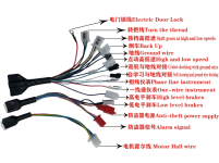
All the wires for the hall and 3 phase are color coded, so everything shud be wired fine.

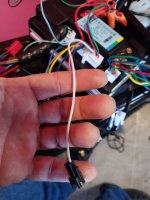
Cept there is one white hall wire coming from the motor that the controller didnt have.
OK, good sign, but pump the brakes so you don't accidentally fry something. The symptoms are consistent with the hall and phase wire combinations being incorrect, but there's simplified method for correcting them without going through the 36 combinations, one of which is correct.

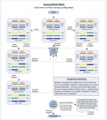
Study the chart posted by a member of this forum, that's about 1/3 of the way down the page on this link:

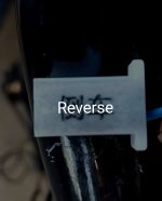
A "stuck" motor means a condition where the motor doesn't turn at all. If it's turning but noisy, follow the flow chart to make the suggested changes (seems like you may be in the top middle box if the motor is turning, and need to move to the top right box next; if it's not turning, then you'd go to the left box). There is one combination that will run smoothly forward, and one that will run smoothly backwards; so you want to get it running smoothly first, then reverse the direction if necessary.
 
You talking about this graph? Looks like the hall wires are all hooked up correctly, just wrong phase combination. This explains the "stray" white wire coming from the motor as well.
 

Attachments

  • Screenshot_20230925_192717_Chrome.jpg
    Screenshot_20230925_192717_Chrome.jpg
    217.2 KB · Views: 12
Koolsville. So i got the motor turning smoothly with the correct phase config. Im in my trailer 'cause it's warm, i picked the rear end off the floor and goosed the throttle. When i got it running smoothly, i full powered the throttle and it seemed to go to full power, then select a different mode where the wheel started spinning super fast.

I seem to remember reading about a controller selecting mode when it's first hooked up.

Anyway, i went to take it for a spin and it acts as though it is either stuck in an incorrect mode, or something else is going on. Doesnt run smoothly AT ALL with a load on it. I knw i have a tendency to "go for it," so im just chilling in my pad, charging the batt, and waiting for educated instruction.
 
Do you have a wattmeter or ammeter, so that you can see the amps from battery to controller during operation? And a speedometer on the powered wheel?

Do you know about how fast the system should go? Meaning, how fast did it go before changing the controller? It should go about the same speed now.

If so, you can test the various combinations for the lowest current (around a couple of amps or less) offground / unloaded in the right rotation direction, at the correct full speed for the system.

If it goes too fast, it's a false positive.

If it is too high a current, same.

If it has unusual or excessive noises, same.

There will be three correct forward combinations, each of which is really the same, just rotated "forward" by one color.

There will be three correct backward combinations, same.
 
This is how the bike acts: If i try to throttle from a stand still, the motor just shutters. I have to get it going a bit then it will run smooth for a couple seconds, then go back to shuttering and loosing speed.
Sounds like a false positive. I'd follow the flow diagram assuming noisy rotation. If the motor draws more than 70W-80W with the wheel elevated, then it's definitely a false positive and you can damage your motor running it that way.
 
None of them configurations are a positive. Can only get a "false" positive. Been through it 3 times. About to put all the factory stuff back on and have to ride around like a homo with all my special screens and selector buttons and oh yes yes of course you want all that crap!

What is the issue here, guys? There are only so many different parts to this equation and you know all the pieces. What is the issue here?
I re-read you original post. The assumption is that the original controller failed, but that could be a partial diagnosis. I would perform the hall sensor test on the motor, that’s earlier in the linked article, to make sure the motor’s hall sensors are still all good. One of them might have gotten cooked.
 
You win nicobie!!!
The motor core has been replaced with a new 1000w motor core. All is good there.
Nothing on the flow chart is a true positive. What do i do now? Most i can figure is to spend a day going through all of the configurations. That'll be my 2mrrw.
 

Attachments

  • Screenshot_20230925_192717_Chrome.jpg
    Screenshot_20230925_192717_Chrome.jpg
    217.2 KB · Views: 1
Last edited:
Is there a self learning wire on this controller ? It's usually one single wire (maybe white) with a 2pin jst black . But that can n also be a speed limiter wire.
If a motor is running to fast it may be to advanced as timing on a car. Hard to run with load.
Is this a sensor and senseless controller dual mode ?
Good luck
 
Possibly three modes.

Sensorless/sensored i do not know.

At this point i've tried every possible phase wiring config and got two false positives.

If unhook the hall wire connector then the motor no turn but barely rotating with no sound.

(PICS)
These are the wires with chinese marks i have translated.
There are some other wires with no writing.
There is this white wire with black connector.
 

Attachments

  • Screen Shot 2024-03-08 11.42.07.jpg
    Screen Shot 2024-03-08 11.42.07.jpg
    123.5 KB · Views: 4
  • Screen Shot 2024-03-08 11.41.46.jpg
    Screen Shot 2024-03-08 11.41.46.jpg
    106.6 KB · Views: 1
  • Screen Shot 2024-03-08 11.50.54.jpg
    Screen Shot 2024-03-08 11.50.54.jpg
    114.7 KB · Views: 2
  • Screen Shot 2024-03-08 11.51.23.jpg
    Screen Shot 2024-03-08 11.51.23.jpg
    120.3 KB · Views: 1
  • Screen Shot 2024-03-08 11.51.43.jpg
    Screen Shot 2024-03-08 11.51.43.jpg
    90.2 KB · Views: 3
  • 20240308_114246.jpg
    20240308_114246.jpg
    1.3 MB · Views: 3
The three-speed switch I know have three wires the throttle has three wires the whole sensor has five wires red black green yellow blue and maybe coming out of the motor a white wire which would be for a temperature wire. It looks like those ones with the red plastic or alarm and maybe a phase wire lock for the motor. Maybe.
Contact the seller and ask for a wiring diagram in English
 
Back
Top