controller power for light kit

Metabo

1 mW
Joined
Apr 21, 2024
Messages
19
Location
Oakdale Minnesota
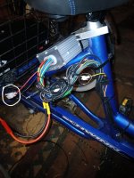
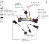
The molex on the left is what I believe to be a power connector from the controller. The molex on the right is the power connector from the light kit. How do I confirm this and which color wires are - +. From the controller it's red/black and from the light kit it's yellow/black I can change the molex's so these can be connected, but before I do, I need some help.
 

Attachments

  • controller.jpg
    controller.jpg
    195.9 KB · Views: 8
Last edited:
First you'll need to verify the voltage output from the wires you want to use on the controller to make sure they are what your light kit needs. Your multimeter will also tell you the polarity of the voltage on the wires; if you have the meter positive on the voltage negative it will show you a - sign.

The manual for the light kit should tell you what voltage it requires, and how much current (amps) it will need. If you don't have this information, you need to get it before you proceed.

If the controller wires you show are not from a part of the controller designed to supply that much current, it will probably damage the controller. If you don't know if it is or isn't able to supply that current, don't use it to try to do this.

If the controller has a display that turns it on, then anything that runs off any power from the controller (except off the main thick battery wires) pulls that current thru the display itself, which can only handle a tiny current in it's internal switch, so running anything other than the controller from that risks breaking your display in a way that keeps your controller from turning on and working.
getting ready to use the voltmeter now on the red/black wires coming form the controller I will check the specs on the light kit. I'm guessing the voltage should be low for the light kit, like 5v or less. The power connector from the light kit is yellow/black and I don't know which is + or -.
 
If you have a link for the controller, folks here may be able to recognize it and advise on whether or not the lighting circuit can provide sufficient current. Many can only provide enough to supply a relay for a lighting circuit.
 
Some of the ebike light's have a built in Converter to drop the voltage.Other wise you need a DC to DC Converter to drop voltage to the light's voltage.I wouldn't connect it to the controller for the risk of damage to the controller
 
getting ready to use the voltmeter now on the red/black wires coming form the controller I will check the specs on the light kit. I'm guessing the voltage should be low for the light kit, like 5v or less. The power connector from the light kit is yellow/black and I don't know which is + or -.
Unless you don't care what happens, you shouldn't just guess what the kit needs and connect it to something and hope; you could start a fire in the wiring or electronics, or blow up your controller, battery, etc.

Same thing for wiring polarity, current draw, etc.

If the light kit doesn't have instructions that tell you these things, and you can't get that info from the seller, you'll either have to disassemble it to reverse engineer it to find out what you need to know (if you know enough electronics to figure out how it works and how much current it will take and what voltage it needs to run), or return it and buy a kit that does have that info, and is compatible with the stuff you have.

If you have enough money to replace the controller, light kit, battery, wiring, etc., when it gets damaged due to a simple lack of information...you could just spend that money on a kit that has the info instead. ;)
 
If you have a link for the controller, folks here may be able to recognize it and advise on whether or not the lighting circuit can provide sufficient current. Many can only provide enough to supply a relay for a lighting circuit.
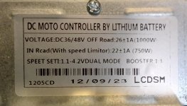
The controller was part of a e-wheel kit.
 

Attachments

  • controller type.jpg
    controller type.jpg
    78.2 KB · Views: 5
Some of the ebike light's have a built in Converter to drop the voltage.Other wise you need a DC to DC Converter to drop voltage to the light's voltage.I wouldn't connect it to the controller for the risk of damage to the control

If you have a link for the controller, folks here may be able to recognize it and advise on whether or not the lighting circuit can provide sufficient current. Many can only provide enough to supply a relay for a lighting circuit.
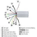
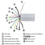
I managed to find this and as it shows the red/black coming from the controller is in fact for the light. Now I just need to figure out the polarity on the yellow/black wire from the light kit.Screenshot 2024-04-22 012400.png
 

Attachments

  • ebc-48v1000wc-1.jpg
    ebc-48v1000wc-1.jpg
    224.4 KB · Views: 6
Last edited:
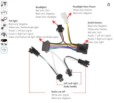
Well I finally found the info I needed. The pictures now clears this up. I used a voltmeter to find polarity for #1 LED light power per controller picture and the wire harness for the light kit shows the positive and negative for the power hook up. I think I'm good to go. I'll have the o'fire extinguisher on standby........lol

Cheers everyone
 

Attachments

  • ebc-48v1000wc-1.jpg
    ebc-48v1000wc-1.jpg
    224.4 KB · Views: 12
  • Screenshot 2024-04-22 020219.png
    Screenshot 2024-04-22 020219.png
    714.1 KB · Views: 12
Well I finally found the info I needed. The pictures now clears this up. I used a voltmeter to find polarity for #1 LED light power per controller picture and the wire harness for the light kit shows the positive and negative for the power hook up. I think I'm good to go. I'll have the o'fire extinguisher on standby........lol

Cheers everyone
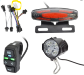
Well with that information I got the light working, but not as it should. Headlight turns on, but no running light for the tail light. Signals work only when holding the brake handle in. Tail light only lights up when the brakes are applied. Could be the controller is not talking to the light kit very well. After all that work I just had to laugh.

Cheers
 
Seems like the tail light unit is miswired internally. The running light and turn signals should be picking up their ground from the black wire of the connector, and only the brake light should be using the switched white brake signal ground. It may be possible to fix that if you are able to open the tail light and willing to do some soldering, if it’s just swapping wires. If those connections are integrated into the circuit board then you’re probably SOL.
 
I have a similar light kit. There was mention that the brake connection may need to be reversed. I had to do this on my light kit as well. The connection from the brake sensor input had to be reversed. I depinned the male ends that connect to “brake cut-off” of the harness and the brake then worked. Check the description for your kit. Doesn’t it mention reversing the brake cutoff?
 
I have a similar light kit. There was mention that the brake connection may need to be reversed. I had to do this on my light kit as well. The connection from the brake sensor input had to be reversed. I depinned the male ends that connect to “brake cut-off” of the harness and the brake then worked. Check the description for your kit. Doesn’t it mention reversing the brake cutoff?
To tell the truth I've not seen that post, but that info gives me something to run with in my search. Thank you very much, Google here I come.....................................................again...lol

Also a gamer. IL-2 Battle of Stalingrad
 
I have a similar light kit. There was mention that the brake connection may need to be reversed. I had to do this on my light kit as well. The connection from the brake sensor input had to be reversed. I depinned the male ends that connect to “brake cut-off” of the harness and the brake then worked. Check the description for your kit. Doesn’t it mention reversing the brake cutoff?
Do you have any pictures???
Thanks Metabo
 
I have a similar light kit. There was mention that the brake connection may need to be reversed. I had to do this on my light kit as well. The connection from the brake sensor input had to be reversed. I depinned the male ends that connect to “brake cut-off” of the harness and the brake then worked. Check the description for your kit. Doesn’t it mention reversing the brake cutoff?
can you use this diagram to show me what wires you moved?
 

Attachments

  • Screenshot 2024-04-22 020219.png
    Screenshot 2024-04-22 020219.png
    714.1 KB · Views: 3
I have a similar light kit. There was mention that the brake connection may need to be reversed. I had to do this on my light kit as well. The connection from the brake sensor input had to be reversed. I depinned the male ends that connect to “brake cut-off” of the harness and the brake then worked. Check the description for your kit. Doesn’t it mention reversing the brake cutoff?
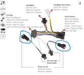
I Reversed the black and white in the two circled wires. With the controller turned on I now have headlight, tail light and turn signals but no brake light. With the headlight turned off I have no tail light but the signal lights work. When the tail light is on it's so bright it makes me think that it's the brake light not the running light. At least your suggestion got more working than was working before. Now I just need my brake light and running light to work.
 

Attachments

  • Reverse Black and White.png
    Reverse Black and White.png
    735.9 KB · Views: 7
The tail light and signal lights should internally be using the constant ground instead of the switched ground, the same black wire as Headlights and Headlight Horn Power use. Swapping the plug wires created a constant ground, so they both work, but also keeps the brake light on constantly as well.
 
I Reversed the black and white in the two circled wires. With the controller turned on I now have headlight, tail light and turn signals but no brake light. With the headlight turned off I have no tail light but the signal lights work. When the tail light is on it's so bright it makes me think that it's the brake light not the running light. At least your suggestion got more working than was working before. Now I just need my brake light and running light to work.
Those were the connectors that I was referring to. I also remember adding a ground, however, I don’t remember where I got the ground from. I was testing and trying, then it worked and I left it.
 
Those were the connectors that I was referring to. I also remember adding a ground, however, I don’t remember where I got the ground from. I was testing and trying, then it worked and I left it.
lol You will take that secret to the grave with you. I ordered another tail light for this kit because while removing a zip tie I cut the black and white wire on the lead that comes from the tail light. I reconnected them but they were cut so close to the molax that the connection is not reliable. The tail light I ordered has the same molax and the wires are the same colors.

 
Last edited:
Haha. I’d like to say that I used the ground from the display, but that may be wrong. I’m kicking myself for not documenting what I did. I did lots of testing and trying. One of these days (that im not working and don’t have family life things) I’ll get back in my bike and write it all out.
 
Haha. I’d like to say that I used the ground from the display, but that may be wrong. I’m kicking myself for not documenting what I did. I did lots of testing and trying. One of these days (that im not working and don’t have family life things) I’ll get back in my bike and write it all out.
I'm 74 years old and retired. I wake up in the middle of the night thinking about this stuff, thus my middle of the night questions. Trying to get this thing going for my little lady and she's looking at me with a raised eyebrow thinking bit off a little more than you can chew this time didn't you oldman. I'm not too good when it comes to electrical things but I will muddle through this.

 
Some of the ebike light's have a built in Converter to drop the voltage.Other wise you need a DC to DC Converter to drop voltage to the light's voltage.I wouldn't connect it to the controller for the risk of damage to the controller
I was able to find out what all the wires from the controller were and also others have done the same hook up as well. So power has been applied but if you have been following this thread you know I'm still working through some other problems with this kit.
Thank you so much for your reply
 
Unless you don't care what happens, you shouldn't just guess what the kit needs and connect it to something and hope; you could start a fire in the wiring or electronics, or blow up your controller, battery, etc.

Same thing for wiring polarity, current draw, etc.

If the light kit doesn't have instructions that tell you these things, and you can't get that info from the seller, you'll either have to disassemble it to reverse engineer it to find out what you need to know (if you know enough electronics to figure out how it works and how much current it will take and what voltage it needs to run), or return it and buy a kit that does have that info, and is compatible with the stuff you have.

If you have enough money to replace the controller, light kit, battery, wiring, etc., when it gets damaged due to a simple lack of information...you could just spend that money on a kit that has the info instead. ;)
I know you are an admin, but I reported this message as demeaning.
 
Seems like the tail light unit is miswired internally. The running light and turn signals should be picking up their ground from the black wire of the connector, and only the brake light should be using the switched white brake signal ground. It may be possible to fix that if you are able to open the tail light and willing to do some soldering, if it’s just swapping wires. If those connections are integrated into the circuit board then you’re probably SOL.
I ordered another tail light so now I may open up the bad tail light and see if your idea helps. Thank you for your help
 
I know you are an admin, but I reported this message as demeaning.
My apologies, it was not meant to be. We get a fair number of complete newbies here that assume things work a certain way without checking anything, and then are upset (sometimes at us) when things blow up even after they just keep telling us they "guess" that things work that way. Your responses suggested this was another case of that, so I spoke "sternly" trying to show what could happen by doing this, to help prevent you from damaging your parts and wasting your time/money or worse. I could probably have worded it better.
 
Back
Top