Conversion of a Bultaco Sherpa

After a break due to too much work, I want to see now what the controller does (or not does) when activated again.

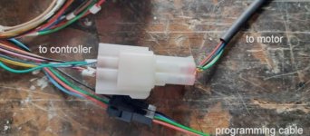
Can I switch it on for a first test by only connecting the thin "pwr" and "ground" cables in the plug (pink and black)
to my power source:

Controller-Motor-plugs-text.jpg

or is it absolutely necessary to connect also the fat phase wires of the motor and the main battery cables?
 
Great I've been waiting for news for a long time 👍.
The thin power cable will not suffice as it is only the wire for the On/Off switch. it needs a direct power supply to the controller too.
At first you should just hook it up to a weak power supply with a small fuse just to see if you can hook up your computer and check the fault codes.
If the faults are normal, voltage too low or motor fault then you will have to connect your controller to the battery and the motor phases to do a real operating test, always using a very weak fuse for safety. If everything is ok you can plug it in permanently.
 
PITMIX said:
The thin power cable will not suffice as it is only the wire for the On/Off switch. it needs a direct power supply to the controller too.

So I should connect my power supply to the large plus/minus connectors on top of the controller
AND the thin power+ground cables which lead to the plug in the picture?

Sorry if I am asking stupid questions, but I have never tested the controller alone.
When I started the build, I always had the controller AND the motor connected...
 
Yes, you have to connect the power supply as if it were connected to the motorcycle, but without the motor. The controller needs a +/- power supply and ON/OFF contact.
One thing bothers me, in your photo you show the motor hall sensor connection. I hope that's a mistake.
 
It's ok for wires +/- :thumb:
 
Elektrosherpa said:
This is the plug with the "power" cable (pink, for switching on/off)
In this case there is an error on what you wrote on the photo. On left side the pink wire is ON/OFF to the controller and on the roght side it isn't the motor but a switch on the handlebars.
If you connect the On/Off wires in this way to the motor connectors then you should not be surprised that the probe indicates nonsense and that the controller is burned. Hall sensors must be burned also.
 

Attachments

  • IMG_20220719_083905.jpg
    IMG_20220719_083905.jpg
    184.7 KB · Views: 1,185
I have been doing a first test.

Just connected the big plus and minus connectors, and the thin "power" cable to my adjustable power supply:
TestingSetup.jpg

Next I tried to connect the Kelly software, and it worked:
TestingKellySoftware-Monitoring.jpg

Of course "hall error", because the cables are not connected.
And a temperature reading which is obviously wrong.
But the voltage reading was correct (61 V is the maximum my power supply can deliver).

The controller did not emit error beep codes.

And (according to the display of my power supply) the controller's power consumption kept changing between 0.1 A (0.6 W) and 0,2 A (1,2 W).
Testing-PowerConsumption1.jpg Testing-PowerConsumption2.jpg


If I remember right, this was not the case before the "flash" incident.
At start-up it used to be a little higher, and then it was staying constant.
 
The fact that you can hook up your computer and read the settings is a good thing. Now you will be able to connect the motor and put a very weak fuse on the battery for safety.
If I were in your place I would take the opportunity to put an adjustable resistor in place of the motor probe on the controller connector. This would allow you to test the ohmic value that corresponds to what your controller requires for a good measurement. If you can't, disable the motor thermal protection function in the controller settings.
 
It depends on whether the thermal protection function is activated or not.
You can make a shunt with a small piece of wire on the connection of the probe to see if the value changes.
 
PITMIX said:
Now you will be able to connect the motor and put a very weak fuse on the battery for safety.

What is a fuse which is weak enough, in your opinion?
And - can I use a 12V car fuse ???
I dont have any fuses for 72 V except the big 200 A fuse which came with the controller...
(see controller picture above)
 
Yes, a 5A car fuse will be fine just to run the engine off-load. It shouldn't snap if the capacitors are precharged properly. Maybe if you run the engine slowly, it won't burn out. If this first test is conclusive, you can increase the fuse by putting a 30A model to make the motor run faster when idle. If it is ok then the final connection can be made.
 
It doesn't work.

Today I put the controller back into the bike and re-connected everything.
Just the battery "+" not directly to the controller, but with a 30 A fuse in the line.

When I tried with the adjustable power source (which can do maximum 60V and 5A),
there was a sound, like a weak buzz,
and the Ampere/Watt displays of the power source showed varying values-
so it was trying to do something.
But the motor didn't react to the throttle.

Next I tried to hook up the battery (actually charged to ~74 V),
again with the 30 A fuse in the positive cable.

I could precharge, and switch on the controller (by the "ignition" key), without problem.

But as soon as I moved the positive switch
(as described earlier, I have a manual switch in both main power cables from battery to controller),
the 30 A fuse blew up.
 
Now that you have a small fuse you can do other tests. Use a smaller fuse it will be less risky for the controller. Maybe the flash you did put the + of your switch and the mass of the motorcycle in contact. Check for a short on that side.
I think you didn't check if the mosfets were shorted.
You can also measure the continuity between the U-V-W terminals with the power off and with the motor phases disconnected.
 
Also I think the problem is in its commissioning circuit.
 
PITMIX said:
Maybe the flash you did put the + of your switch and the mass of the motorcycle in contact. Check for a short on that side.
You mean my big manual switch for the "+" battery cable ?
Cant imagine that, because it is sitting on a pertinax plate, but I will check it.

PITMIX said:
I think you didn't check if the mosfets were shorted.#
No, I didnt, because I have no idea how to do that...

PITMIX said:
You can also measure the continuity between the U-V-W terminals with the power off and with the motor phases disconnected.
What kind of measurement should I do there?
"beeping" with multimeter, to see if there is an internal connection between two of them?
 
j bjork said:
Measure between U V W and B+ and B- on the controller with disconnected phase and battery wires.
Not just between phases, I dont think that will show shorted mosfets.

You mean I should just use the "beep" function of the multimeter,
which is meant for checking electrical connections if current is passing through?
 
OK, I measured the resistance between all possible combinations of the controller screws (connectors).
(W was the contact where the "spark" happened )

Here the results:

U -> W = 175 k Ohm
U -> V = 145 k Ohm
U -> B+ = 4.2 M Ohm
U -> B- = 69 k Ohm

V -> W = 154 k Ohm
V -> B+ = 80 k Ohm
V -> B- = 50 k Ohm

W -> B+ = 110 k Ohm
W -> B- = 100 k Ohm

B+ -> B- = 20 M Ohm
 
The ohmic values ​​you get don't seem to show a dead short. If you have the same values ​​between U-V and U-W and the value is also the same between V-W then surely there is no problem on the mosfets. Normally it is necessary to check the value on each of the legs of the mosfets but I do not think that the problem is at this level because otherwise the disjunction would occur during acceleration and not as soon as the controller is switched on.
Ditto for the value between B+ and B- which is very high, this proves that there is no short circuit at this level. On the other hand you do not say anything about the value between the +VCC and the GND or B-.

Sherpa said:
I could precharge, and switch on the controller (by the "ignition" key), without problem.

But as soon as I moved the positive switch
(as described earlier, I have a manual switch in both main power cables from battery to controller),
the 30 A fuse blew up.

I don't understand your ignition method. How can you turn on the controller with the ignition key if the Master Ignition Button is not ON ?
You must first precharge the capacitors then immediately activate the large activation button of battery and only then activate the ignition key.
The precharging of the capacitors is used to avoid burning the large battery activation button and also to slowly charging the capacitors.
If you charge the capacitors then you turn the key, meanwhile the capacitors are discharging. Then you activate the battery button, it's as if the precharge was useless.
No wonder the fuse blows under these conditions.
 
How big would you estimate the probability that the problem is the motor, not the controller?

I am asking, because I broke my leg (walking....) and I will be immobilized for at least 6-8 weeks. :cry:

This would be an opportunity to order a new controller.
But I would not want to do this, only to find out that it was not the problem, when it finally arrives ...
 
Sorry to hear about your leg. You have had to deal with a bunch of issues and many people would have walked away from this project. Since everything takes so long to be delivered, I would order both new controller and motor and whatever else could possibly be wrong with the bike. You tried the package deal from china, trusting that the vendor knew what would work well together and you ended up with nothing but problems.

Now that you know more about motors, controllers, venders etc, you can buy individual components or a paired set that are more likely to work together out of the box. The pair you have now never really worked well and that was before you had a plasma ball incident.
 
Back
Top