Conversion of a Bultaco Sherpa

I also think the points "thoroughbred" made about the "NC" and "B+" connectors are reasonable.
Indeed the screw labelled "B+" was fixed, and the one on "NC" was loose.

So today I connected the necessary cables, as "Dui, ni shuo de dui" suggested, and I connected my source PLUS to "NC".
After connecting the "PWR" wire to the source, too, the bluetooth thing indeed started blinking,
and I could connect as well the smartphone as the laptop.

The software still looks kind of crappy on the smartphone, nothing fits, and the screen orientation cannot be changed.

But on the laptop it looks fine.

The parameters were already set, e.g. the angle was already to "85" as it should be.

In this "idle" state, my power supply indicated only very low power consumption (just about 0,025 A), so I dared to turn the throttle - and - tataaaa... the sprocket started to spin. I carefully turned it more, until up to 4,5 A (what resulted in a motor rotation rate of close to 3000 rpm), without any signs of weakness or failure.
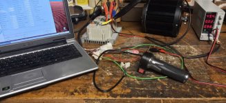
Testing.jpg

Therefore again MANY THANKS to all the helpers ! :bigthumb:

Now I will have a closer look at the settings, and then the serious (but more familiar to me) work will start:
1) getting rid of the combustion engine
2) putting the motor and the controller into the frame

I already found a mechanical thing which I don't like:
The sprocket which came with the motor sits very loosely on the shaft...
As well axially, as radially, there is way too much tolerance/clearance (not really sure which is the right word).
I guess I could eliminate the axial tolerance by adding shim plates-but the radial clearance ?
 
Be careful, I think I have read that you cant run the motor with the computer connected on the kellys.
But others with experience of them would know for sure.

I think you should get a better sprocket that fits on the shaft, like JTF1263 from JT sprockets.
You can read about it in my ktm thread, and I think there is info in the thread I linked about the motor too.
 
Now, after I got the controller/motor/throttle combo working, I received an email from QS,
confirming that I just need to put together the 6 wire plugs of Motor and Controller,
regardless of the wire colors...

They also answered my question about the display, but not as I wished.

I am quoting:

" Display is not pluged directly to the controller, it have to be working with your outer electrical system.
Only the speed signal need to be connected to the No.8 wire of the controller
The display have to be powered directly from your battery "


That's all...
And of course no wiring diagram.
How shall I know which of the 6 cables of the display serves which purpose?

For being able to show the correct speed, there must be a possibility to set the wheel size and transmission rate.
The speed signal from the motor indicates just the rotation speed of the motor, I guess.
This is of course related to the driving speed, but for displaying this speed,
the display needs to "know" the relation of wheel rotation speed to motor rotation speed,
plus the circumference of the wheel.

I have been searching in the www, but most displays I saw there have got physical buttons, which can be used to make settings.

So all together I am not satisfied with QS.
The good thing is:
They answer emails at all. And the motor, as well as the controller, seem to work.
But selling stuff (like this display) without providing any documentation is poor, in my opinion.
 
How shall I know which of the 6 cables of the display serves which purpose?

You need them to tell you what is what in that, else there is many chances you destroy it during process.

Probably you got this connections:
- Ground
- Positive (Here it will read if the vehicle is on/off and battery state)
- Hall or phase (Here is for speed) some are like you say programable others just have a little pot in the PCB that you can adjust up and down in order to tell you the right speed, needs trial/error...
- Turning lights indicator L
- Turning lights indicator R
- Lights on/off indicator
 
But selling stuff (like this display) without providing any documentation is poor, in my opinion.

They will probably do not have a manual or they may not have it in english.
That is one of the reasons why Chinese products can be cheaper, not because their quality or engineering is bad.
They save time and money on manuals, safety procedures, labels, etc... and they do not certify them either. (Anyway they are improving on that very fast)
You can buy a CE certified product (provably made in China) with same quality but will have to pay 2 or 3 times more.
 
_GonZo_ said:
How shall I know which of the 6 cables of the display serves which purpose?

You need them to tell you what is what in that, else there is many chances you destroy it during process.

Probably you got this connections:
- Ground
- Positive (Here it will read if the vehicle is on/off and battery state)
- Hall or phase (Here is for speed) some are like you say programable others just have a little pot in the PCB that you can adjust up and down in order to tell you the right speed, needs trial/error...
- Turning lights indicator L
- Turning lights indicator R
- Lights on/off indicator

Thanks _GonZo_ for confirming my assumption.

I have been writing an email to "Vito" from the "QS motors" thread, maybe he will give me some more info.

But right now, I guess this display will serve me just for showing the battery voltage.
I have tried to power it up.
Red and black are "+" and "-", as I assumed, and if I connect those, it shows me the battery voltage and the ambient temperature. Below 28 V or so, it stops working. So it seems to be made for my planned voltage (48 or 60V, both are displayed properly).

I absolutely do not need a turning lights indicator (if I will put turning lights at all (what I strongly doubt), I can see them and don't need indicator lights), nor a lights on/off indicator. From my other old motorbikes I am used to pay attention to the switch position for that purpose :D

A speedomoter/odometer function would have been cool, but I have been using the Bultaco for more than 30 years without such a thing-I can continue this way. Anyway I have a smartphone which can help here, if really needed...
 
And one more question:
Can anyone explain me, what this "3 Speed Switch" on the throttle is supposed to do?

In the Kelly Controller Manual, I find this:
"(23)Three Gears switch: It is used for function of F-N-R control.
Please check the wiring diagram in the manual for F-N-R control."

I interpret those three letters as "F=forward, N=neutral, R=reverse".
Is that correct?
 
I got a reply from QS.
Very interesting.
Here a quote of the most important parts:

"We're Taizhou Quanshun Motor Co., Ltd., QS Motor in short, now our company name change to Taizhou Quanshun Electric Drive Technology Co., Ltd.
SiAECOSYS (SIA in short) is the sub-brand of QSMOTOR, who focus on electric motor & motor kits as electic powertrain of electric 2/3/4 wheelers, for internantional market.
Official web, http://www.cnqsmotor.com/en/
International sales: Steven/Vito/Damon/Carrie/Judy/Vincent/Summer/Jasmine/Tessio.
There is no company called QS MOTOR LIMITED, the web site https://www.qs-motor.com or http://www.qsmotor.com/ is handled by trading company (QS domestic dealer).
Please note, we/export dept. #SiAECOSYS #QSMOTOR could not deal with after sale issue, if the motor not sold by us or our authorized dealers directly. As the domestic dealer is in contact with our domestic sales, which not belong to our sales performance.
Regarding our powertrain, we prefer VOTOL controller with DKD speedometer.
"

Let me sum this up in my own words:
The company where I bought my stuff is the dealer for China only.
(Don't now why they sell and send to Europe, then).
They sold me a combination which is not recommended by the producer.
If this China dealer does not grant support, the producer won't do this either.


So my advice to all:
Take care not only WHAT you buy, but also WHERE you do this...

Generally speaking, I find this a strange kind of business behaviour.
Here in Europe, a producer would not accept a domestic dealer who sells stuff to other destinations...
 
First of all:I made a mistake when i posted the link to the controller manual this is the correct one:
https://kellycontroller.com/wp-content/uploads/kls-nm/KellyKLS-N-UserManualV2.7.pdf
(I thought you were using a KSL instead of a KLS, little difference in the name, but big in the what are they... and how they work)
Sorry, for this mishap. :oops:
Please check this one as it is quite different than the other one I posted.


About the display:
If you can take good pictures of both sides of the PCB inside of the display case, we may be able to help you with it. I have installed some of them and I was able to find out how to make them work properly.


Can anyone explain me, what this "3 Speed Switch" on the throttle is supposed to do?
The 3 speed switch is just a 3 position switch :lol:
It can be used as for F-N-R function (usefull in a car, boat, etc.) or as a 3 speed Low-Medium-High switch, or as anything else you want in your bike.
It is not mandatory that you use it with the controller.
 
_GonZo_ said:
First of all:I made a mistake when i posted the link to the controller manual this is the correct one:
https://kellycontroller.com/wp-content/uploads/kls-nm/KellyKLS-N-UserManualV2.7.pdf
(I thought you were using a KSL instead of a KLS, little difference in the name, but big in the what are they... and how they work)
Sorry, for this mishap. :oops:
Please check this one as it is quite different than the other one I posted.
Thank you. I had this already.
As I wrote, I got this KLS Manual now in Version 2.5, 2.6 and 2.7 :roll:

_GonZo_ said:
About the display:
If you can take good pictures of both sides of the PCB inside of the display case, we may be able to help you with it. I have installed some of them and I was able to find out how to make them work properly.
That would be cool.
As I said, I dont need it urgently - but if I could make the speedometer work, it would be nice.
Will have a look if I manage to open the case without destroying it.
Hope it is not glued, as this cheap chinese stuff is often...

_GonZo_ said:
Can anyone explain me, what this "3 Speed Switch" on the throttle is supposed to do?
The 3 speed switch is just a 3 position switch :lol:
It can be used as for F-N-R function (usefull in a car, boat, etc.) or as a 3 speed Low-Medium-High switch, or as anything else you want in your bike.
It is not mandatory that you use it with the controller.
Sure I will not use it as a reverse switch-I find the position at the handelbar too dangerous for such a function-I think it could happen here that I switch to reverse by mistake ...

But how would a slow-medium-high speed switching work?
For my purpose (a lot of dirt track driving with my sighthound) this could maybe make sense ...
 
But how would a slow-medium-high speed switching work? For my purpose (a lot of dirt track driving with my sighthound) this could maybe make sense ...

The controller has to have that capability. Some of them have one or more extra wires for limiting speed.
 
Sure I will not use it as a reverse switch-I find the position at the handelbar too dangerous for such a function-I think it could happen here that I switch to reverse by mistake ...

Do not worry about it, it has safety systems that will not reverse the motor until it has not stoped and throttle pass through 0 position. But I do not think reverse is much of use in a small bike like that.

But how would a slow-medium-high speed switching work?
For my purpose (a lot of dirt track driving with my sighthound) this could maybe make sense ...

Think of it like a "ECO-NORMAL-SPORT" switch. I think this is very useful, handling so much instantaneous torque can be tricky in slow areas like city driving.
 
_GonZo_ said:
But how would a slow-medium-high speed switching work?
For my purpose (a lot of dirt track driving with my sighthound) this could maybe make sense ...

Think of it like a "ECO-NORMAL-SPORT" switch. I think this is very useful, handling so much instantaneous torque can be tricky in slow areas like city driving.

My controller seems to support this function. In the manual I found this listing:

(12) FWD: Forward switch or can be enabled as High speed switch function. White
....
(22) ECO: Low speed switch function. Blue

So I could just connect cable 12 and 22 to this 3 way switch,
make the appropriate settings in the controller software,
and it will work?
 
So I could just connect cable 12 and 22 to this 3 way switch,
make the appropriate settings in the controller software,
and it will work?

Yes it will work. You will have to activate it in the software as well. The is a field were you can define it:
"Three speed": This item is used to enable or disable three speed function. By default, it is at 0.
0: Three speed function is disabled. 1:Two speed function. 2:Three speed function is enabled.
(Form the manual)
 
Thanks for the reply.

Sorry if I am appearing stupid, but I must ask again:

1) I activate "3 speed function" in controller software

2) I connect cable 12 to one connection of the switch, cable 22 to another one-
and what do I connect to the third connection?

In the manual, I don't find any information about the 3-way-switch they sent me...
 
Elektrosherpa said:
In the manual, I don't find any information about the 3-way-switch they sent me...

You have to find out with a multimeter how the switch is acting (use the continuity function or resistors function in the multimeter), before connecting it.
 
The 3 speed switch has choices. The center leg of the switch should have 12V on it. the other two legs will go to pin 12 and 22. Here is an excerpt I sent to Kelly because there manual is not in proper English, and stuff missing.

Like the Maps (Throttle or Current ramps) why isn't that in there. The Three Speed Switch refers to Figure 4.1, but it is actually Figure 4.2, but the chart is not complete Pin 12 to 12V is High Speed, Pin 22 to 12V is Low speed, and both off is Medium speed. Pin 22 is not mentioned in the chart and Medium is not mentioned in the chart. That information is somewhere else in the manual.

You then enable the 3 speed as it is explained in earlier posts.

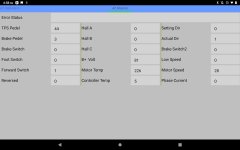
Here in the monitor screen, you can see what speed you have selected. In this screen I have the 3rd (or Fastest) speed selected. "Forward Switch" is selected and or "1" and "Low Speed" is "0"

Screen Monitor OC.jpg

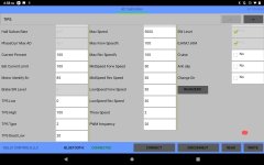
Here are the Speed settings. Unfortunately you cannot set the torque ramps or power in the setting, only a percentage of the full power.

Screen 1b OC.jpg

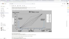
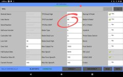
I am searching for maximum power out of my Kelly KLS 72701, and there are many things you can change, but I cannot get maximum power when I want it. Here are the Throttle or current ramps, and my selection on the chart is 80.( circled in red in the Screen 1a )

Throttle Curves.jpg

Screen 1a.jpg

I have spent a lot of time and emails to Fany at Kelly. He is helpful, but the Kelly Controller is limited. I hope this helps.

Don
 
Maico4 said:
The 3 speed switch has choices. The center leg of the switch should have 12V on it. the other two legs will go to pin 12 and 22. Here is an excerpt I sent to Kelly because there manual is not in proper English, and stuff missing.

Like the Maps (Throttle or Current ramps) why isn't that in there. The Three Speed Switch refers to Figure 4.1, but it is actually Figure 4.2, but the chart is not complete Pin 12 to 12V is High Speed, Pin 22 to 12V is Low speed, and both off is Medium speed. Pin 22 is not mentioned in the chart and Medium is not mentioned in the chart. That information is somewhere else in the manual.

You then enable the 3 speed as it is explained in earlier posts.

Here in the monitor screen, you can see what speed you have selected. In this screen I have the 3rd (or Fastest) speed selected. "Forward Switch" is selected and or "1" and "Low Speed" is "0"

Screen Monitor OC.jpg

Here are the Speed settings. Unfortunately you cannot set the torque ramps or power in the setting, only a percentage of the full power.

Screen 1b OC.jpg

I am searching for maximum power out of my Kelly KLS 72701, and there are many things you can change, but I cannot get maximum power when I want it. Here are the Throttle or current ramps, and my selection on the chart is 80.( circled in red in the Screen 1a )

Throttle Curves.jpg

Screen 1a.jpg

I have spent a lot of time and emails to Fany at Kelly. He is helpful, but the Kelly Controller is limited. I hope this helps.

Don

Great post! This helps me a lot!
 
_GonZo_ said:
About the display:
If you can take good pictures of both sides of the PCB inside of the display case, we may be able to help you with it. I have installed some of them and I was able to find out how to make them work properly.

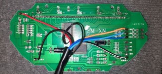
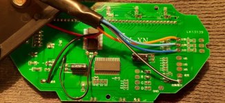
Meanwhile I have opened it and took some photos:

Display-inside-01.jpg

Display-inside-14.jpg

I tried to make everything readable by using different lighting, and by bending the cables to different sides.

The only thing which looks (to me) like "set-able" is this small screw thingy in the left part, labelled "RW1".

What I was wondering about most is this short, black, two-wire cable section leading nowhere (in the center, clearly visible only in 2nd picture).
It is fixed to the board only on one of its ends, the other end hangs lose. The lose end is covered by plastic (no metal wires visible), so it is obvious that it did not just fall off somewhere.
In the second picture I bent it to the other side so that it is visible better.
What is that? An antenna??? But for what?

Searching for the readable inscriptions ("SM-XN" and "LK13139") in the www didn't bring me any results...
 
I am searching for maximum power out of my Kelly KLS 72701, and there are many things you can change, but I cannot get maximum power when I want it. Here are the Throttle or current ramps, and my selection on the chart is 80.( circled in red in the Screen 1a )

This is a profesional controller that can be be matched to the application. So it is normal that it has so manny parameters to tweak. Actually I will like it even with more parameters that what it already has :lol:

The TPS MAPs are in order to create throttle curves, how much power (speed/torque) you will have available in relation with the throttle position. It does not influence in the max power of the motor/controller output, it just changes how it is delivered in relation to the position of the throttle. (See my video I explain about it)

If you want to modify the maximum power output of the motor/controller you have to modify the "Current Percent" and "Battery Limit" fields.
 
Elektrosherpa said:
Meanwhile I have opened it and took some photos:

Display-inside-01.jpg

Display-inside-14.jpg

I tried to make everything readable by using different lighting, and by bending the cables to different sides.

The only thing which looks (to me) like "set-able" is this small screw thingy in the left part, labelled "RW1".

What I was wondering about most is this short, black, two-wire cable section leading nowhere (in the center, clearly visible only in 2nd picture).
It is fixed to the board only on one of its ends, the other end hangs lose. The lose end is covered by plastic (no metal wires visible), so it is obvious that it did not just fall off somewhere.
In the second picture I bent it to the other side so that it is visible better.
What is that? An antenna??? But for what?

Searching for the readable inscriptions ("SM-XN" and "LK13139") in the www didn't bring me any results...

Here we go:
  • Black cable - Ground - Negative of battery
  • Red cable - Positive - Connect to after the main switch so the display activates when it is activated.
  • Yellow wire - Head lights - connect to positive of head lights
  • Blue ones - Turning light - Connect to positive of turning lights, one per each side (Don't know which one is left or right, you will need to test)
  • Black with white stripe - Speed signal - Can be connected to a hall sensor signal output or to a phase cable. In your controller you have a copy of the hall sensors signal that you can probably use Pin8 (Dark Grey)
  • The 2 cables going to a little thingy - That is a thermistor that will give you a temperature reading: ambient temperature, motor temperature, battery temperature... you can install it where you want, just prolong the cables.
In order to adjust the speed you need to dial the little pot. The "small screw thingy in the left part, labelled "RW1"", needs trial and error...
 
Back
Top