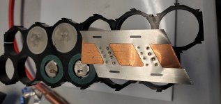
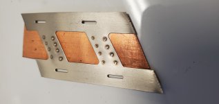
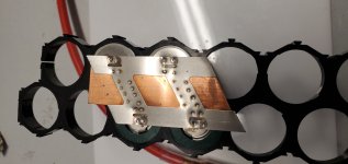
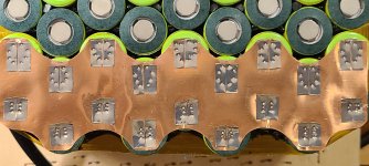
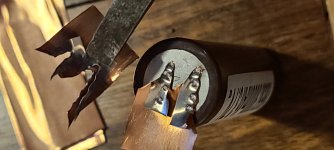
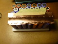
Yes, split copper with "infinite slot" has been done and it helps. More of the current of welding is forced down through the contact points, and less flows through the strip itself.
As a result, less current is needed to get a solid weld. That being said, many pack builders here are happy with 0.10mm thick copper, so the extra trouble of adding infinite slot was not necessary.
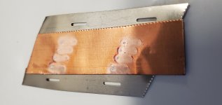
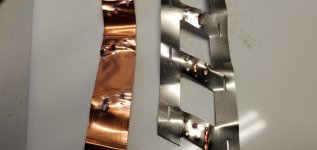
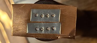
If going to thicker copper, it "might" be worth the effort. The gap can be tiny, and you could use a dot of super glue to connect the nickel-plated steel to the copper, to hold then in alignment for the final weld.
There are some "high amp" 21700 cells that could benefit from 0.15 copper on the series connections, but now we are getting into motorcycle territory.
As a result, less current is needed to get a solid weld. That being said, many pack builders here are happy with 0.10mm thick copper, so the extra trouble of adding infinite slot was not necessary.
If going to thicker copper, it "might" be worth the effort. The gap can be tiny, and you could use a dot of super glue to connect the nickel-plated steel to the copper, to hold then in alignment for the final weld.
There are some "high amp" 21700 cells that could benefit from 0.15 copper on the series connections, but now we are getting into motorcycle territory.