"Copper/nickel sandwich" buses for series connections

I'm using a Malectrics spot welder with a 8ah "50C" 3S HRB LiPo pack

I'm trying to spot weld a sandwich with 0.15mm copper sheet and 0.15 slotted nickle plated steel. The copper and the nickle plated steel are sticking to each other just fine but the two layers are not sticking to the battery cell. Any ideas?
 
Completely split the nickel and copper, then add more amps.

The Malectrics is a precision timer, the type of battery controls how many amps flow in that amount of time.
 
Thanks for the advice, I'm going to try adding another decent 3S in parallel and see what it can do. I understand it will produce better welds but won't splitting the copper sheet/strip increase total pack resistance though?
 
The parallel conections only keep the P-groups voltages between cells balanced, they flow almost no current under all conditions. The parallel connections can be pure nickel, or even steel ribbon.

These battery packs flow their current on the series connections. Visualize two cells you want to connect to make a 2S "8.4V" pack.

Imagine that you spot-weld just two wires from the positive of one cell to the negative of the other. You "could" use one thicker wire, but you decide to use two thinner wires. That image should show you where the split would be.

If you lay a copper sheet across those two electrodes, putting two welding probes onto it means that the path of least resistance is for the welding current to go through the copper sheet, and almost none of it flows through the metal skin of the electrodes.

The nickel-plated steel skin of the cells has high resistance, and the copper sheet has low resistance. We must find a way to force the welding current to flow from one welding probe to the other through the cell tips.
 
john61ct said:
So no copper touches the cells?

Correct. The copper simply serves as a bus for taking 23 separate current sources into one. The cells are indeed spot welded to the nickel strips as per normal.
Last time I tried using nickel coated alumunium busbars but they really tested my spotwelder and actually took longer than the soldering method.
So far solid results.
 
What is the "best" attachment for copper to copper?

Low resistance and high physical strength.

Ideally non-destructively reversible?

Not just for flat strips/sheets, but wire? Fusible links?
 
spinningmagnets said:
...Visualize just two cells you want to connect to make a 2S "8.4V" pack.

Imagine that you spot-weld two wires from the positive of one cell to the negative of the other. You "could" use one thicker wire, but you decide to use two thinner wires. That image should show you where the split would be.
...

Ah ha, I was picturing it wrong; your example clears that up for me. Also; I added another 3S pack in parallel for the spot welder and seem to be getting good welds through both the nickle + copper and onto the cell electrode (40ms pulse time). Thanks spinningmagnets :bigthumb:
 
pwd said:
I'm using a Malectrics spot welder with a 8ah "50C" 3S HRB LiPo pack

I'm trying to spot weld a sandwich with 0.15mm copper sheet and 0.15 slotted nickle plated steel. The copper and the nickle plated steel are sticking to each other just fine but the two layers are not sticking to the battery cell. Any ideas?

What MS setting do you have on the welder?
 
Amperry417 said:
pwd said:
I'm using a Malectrics spot welder with a 8ah "50C" 3S HRB LiPo pack

I'm trying to spot weld a sandwich with 0.15mm copper sheet and 0.15 slotted nickle plated steel. The copper and the nickle plated steel are sticking to each other just fine but the two layers are not sticking to the battery cell. Any ideas?

What MS setting do you have on the welder?

I tried from 25ms up to about 55ms. That was before adding the extra pack in parallel which seemed to make it work well.
 
I got mine fairly fast and cheap on ebay at DIY jewelry websites. 0.10mm easily cuts with scissors.

Just search "copper sheet 38 ga", or "copper sheet 0.10mm"

0.10mm___4-mil__38 ga (equal to 0.40 Nickel)
0.15mm___6-mil__34 ga (equal to 0.60 Nickel)
0.20mm___8-mil__32 ga (equal to 0.80 Nickel)

https://www.ebay.com/itm/181528770437
 
How are batteries made with the copper/nickel sandwich method holding up with time?

I’m working on a mini dirt bike build and am planning to build a pack with Samsung 40T cells in a 20s4p configuration. I need to pull 70A out of the pack, likely near continuous in a race.


Arlo1's post in this thread is the main reason for the question.

Arlo1 said:
I think copper has its place. But I have a stack of liFePo4 that used copper tabs spot welded to the end of the cells and the copper failed to take the repeated stress of heating/cooling/vibrations in the application it was used in. The copper tore holes where all the spot welds were.


Great thread, I've enjoyed reading through all of the 18650/cylindrical cell build threads I could find! Thanks to everyone posting their results here.
 
The cells should be mechanically supported and no physical stress should be put on the tabs. I do understand that the quote specifically mentions that the heat-expansion and contraction of the copper bus was the issue, but...You must design a battery pack to avoid generating heat in the first place. Motors can safely get very hot time after time, and last many years (200F / 93C are common). Even controllers can get VERY warm and remain durable. However, heat in the battery pack should always be avoided.

My cordless drill has several sizes of battery, and the smallest (lightest) version gets warm if I use it constantly for 30 minutes on a job, but it is trying to get the full system amps from the smallest size (2.0-Ah). The 5.0-Ah pack has twice as many cells as the smaller one (ten cells vs five cells). So...why isn't the larger pack 4.0-Ah? Since they are getting the same pack amps from twice as many cells, the amp-draw from each cell is cut in half.

This means they can use cells that have more capacity for a longer run-time (2.5-Ah per cell vs 2.0-Ah). The larger pack doesn't get hot.

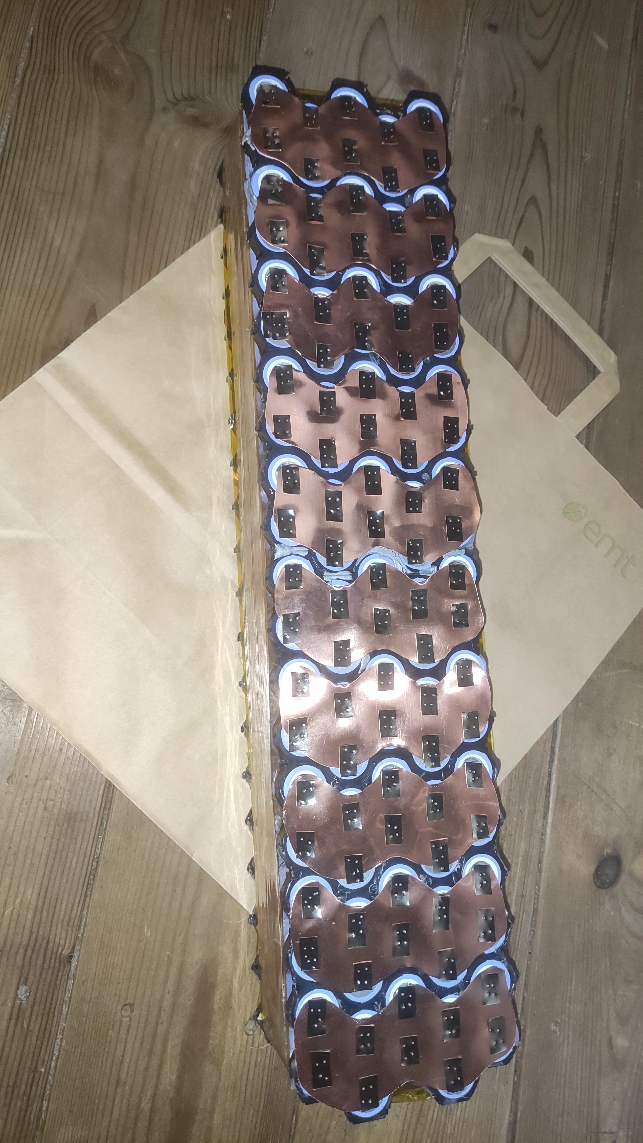
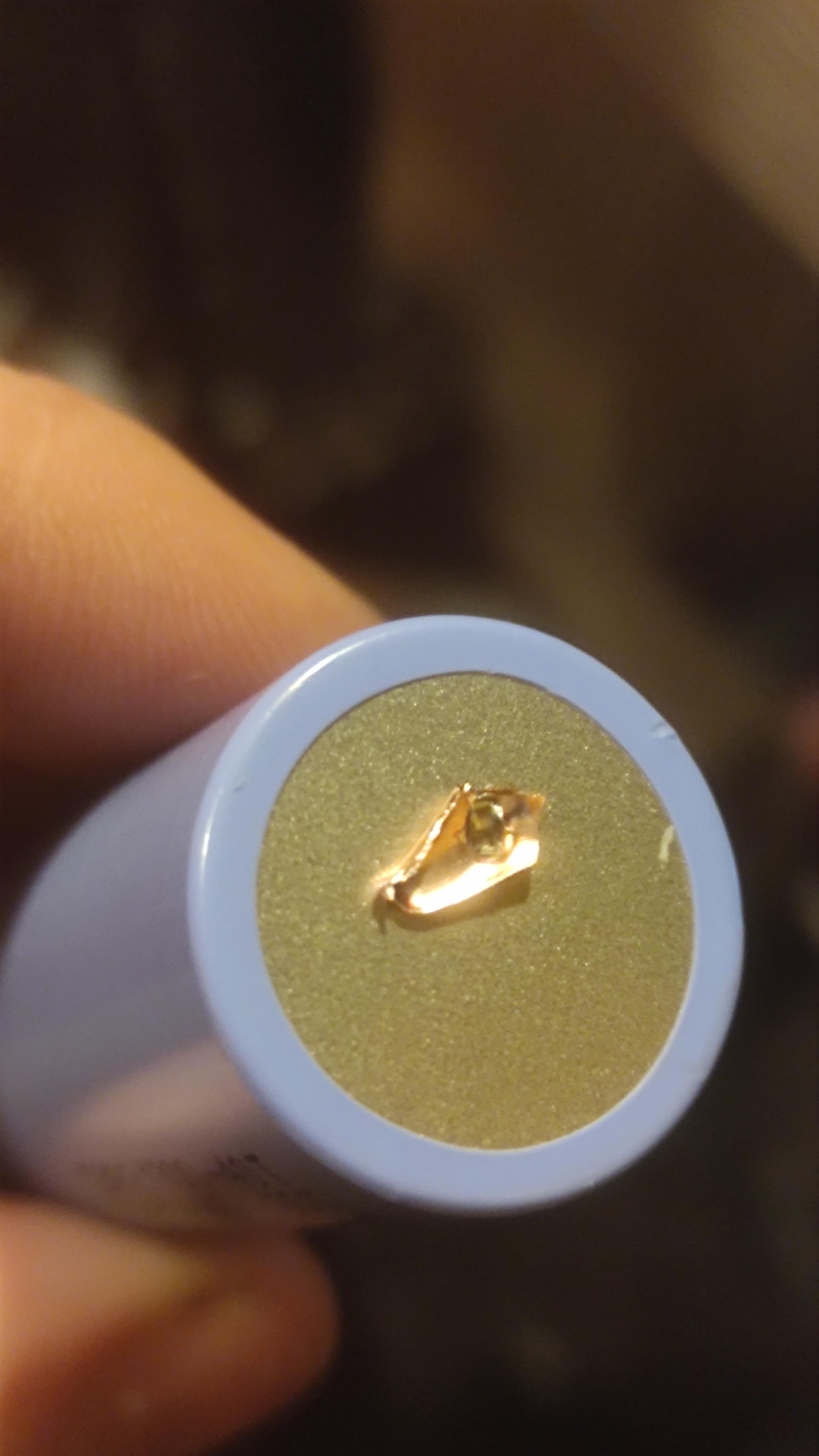
Arlo is experienced, but he doesn't mention the amp-draw from each cell, what temperatures the cell encountered at the spot-weld, or how thick the copper bus was (thicker runs cooler). How deep was the weld? Did he use a nickel or steel cap over the copper tab? What welder was used, and what amount of energy was used in the weld? I believe Arlo is racing this?

It's good that you brought up this issue, but specific issues can have specific work-arounds and solutions.
 
Hi Spinningmagnets,

Thanks for the quick response, those are all good points. It sounds like Arlo1 did mechanically support the cells and I will plan to as well.

The heat expansion and contraction of the copper is something I was interested to get feedback on. As for some short races the battery will be warmed to 45ºC for a lower internal resistance. Battery temps may get up to 55ºC for short periods of time.

I’m happy to hear of people's experiences with this. I can also run some tests as I have load banks for testing batteries that can do up to 540A! :twisted:

I’ve worked on battery pack designs for electric race cars, but those were pouch cells and welding/connecting 18650/21700s is new to me.
 
I don't believe this has been discussed before, but since it addresses a failure point, I am grateful for you and Arlo for bringing this up. I am a fan of the "infinite slot" in the copper buses simply for the help it provides in the welding phase.

I now believe it is even more important because it could allow some flex in the buses, avoiding any stress at the weld-points...
 
Finally had some free time to spotweld the battery I have been planning to make for a while. This is 13S17P pack with LG INR18650-M29. Did extensive discharge tests on the cells and survived 800 cycles without issues. I used kWeld at 70 joules, 0.1mm copper and 0.1mm nickel strip.
Right_Resized.jpg
Left_Resized.jpg
 
Gawjuss!

How are you making the power pair wiring connection to those folded copper tabs?
 
Voltspa said:
That is some beautiful craftsmanship! Did you have the copper laser/water cut? I just hand-cut mine last night and they don't look bad but def won't be as amazing as this.

It was cut with handheld cnc router (Shaper Origin). If I would do it again, probably just send it off to a proper cnc shop. Vinyl cutter was used to cut paper outline with holes for spotwelding accurately.
 
multifrag said:
This is 13S17P pack with LG INR18650-M29. Did extensive discharge tests on the cells and survived 800 cycles without issues.
Your Cu plate/Ni strip build is one of the best yet (IMO) in that you also include and explain the neg/pos 10awg cable connections, and with such clean Professional Presentation Photos WELL DONE ! ... :thumb:

The only downside (if downside) are more cells in parallel (13S17P) needed using only a 100A Controller (17P x 6A = 102A) than with high energy dense cells rated at 15-20A MCD (13S7P). The M29 datasheet says MCD is 6A (not 10A). Whereas only seven VTC6 cells in parallel (7P x 15A = 105A) would be needed using a 100A Controller ($150 more for high energy cells ?) ...

  • 13S 17P(M29) = $750 at $3.26ea for 230 cells (9 extra cells) ... 17P x 6A = 102A
  • 13S 7P(VTC6) = $900 at $9.00ea for 100 cells (9 extra cells) ... 7P x 15A = 105A

A few questions ...
  • What charge/discharge rates did you use resulting in 800 cycles (e.g. charge 0.5C to 4.10V then discharge to 3.20V)??
  • What was your reason for the 1S17P protruding when it wouldn't have been necessary?
  • Assume you're planning on using a 100A Controller?

Bottomline Question: What's the most number of cycles do you think you could achieve with VTC6 15A MCD rating (13S7P high energy dense cells) using your same M29 charge/discharge test(s) (e.g. 0.5C to 4.10V with LVC at 3.20V) ??
 
eMark said:
multifrag said:
A few questions ...
  • What charge/discharge rates did you use resulting in 800 cycles (e.g. charge 0.5C to 4.10V then discharge to 3.20V)??
  • What was your reason for the 1S17P protruding when it wouldn't have been necessary?
  • Assume you're planning on using a 100A Controller?

Bottomline Question: What's the most number of cycles do you think you could achieve with VTC6 15A MCD rating (13S7P high energy dense cells) using your same M29 charge/discharge test(s) (e.g. 0.5C to 4.10V with LVC at 3.20V) ??

  • Charging to 4.1V at 1.5A, waiting for 5 minutes and discharging to 3.1V at 3A. I have a post on ''Li-ion cells cycle ageing'' about these cells
    https://endless-sphere.com/forums/viewtopic.php?p=1596396#p1596396

  • The empty area is for the controller and charger. 18fet Charger and 1000w Eltek flatpack S charger.

  • The ebike is limited by the 9C hub motor. Might change it down the line. The battery was built for range and longevity. By my calculations I should be able to achieve 80 mile range at 30mph. The system won't even see 60A, not to mention 100A. It's a city ebike.

Pajda already tested VT6 cell :
  • https://endless-sphere.com/forums/viewtopic.php?p=1606780#p1606780
  • https://endless-sphere.com/forums/viewtopic.php?p=1692530#p1692530

After 1000 cycles = 78% original capacity
 
multifrag said:
Charging to 4.1V at 1.5A, waiting for 5 minutes and discharging to 3.1V at 3A. I have a post on ''Li-ion cells cycle ageing'' about these cells ... https://endless-sphere.com/forums/viewtopic.php?p=1596396#p1596396
M29 is one of Pajda's favorite 1865 cells (cost per kWh & cycle life). Your M29s $2.43ea :D
multifrag said:
The battery was built for range and longevity. By my calculations I should be able to achieve 80 mile range at 30mph. The system won't even see 60A, not to mention 100A. It's a city ebike.
What's more impressive are the actual c/d 13S17P M29 cycles providing exceedingly many more miles (per charge) than those of a 13S7P VTC6 pack. Less than half as many charges (say 1/3) required than required for a 13S7P (VTC6), if commuting say 20-25 miles round trip daily. Figure conservatively 44Ah (M29) versus 19.5Ah (VTC6) charging to 53.3V (4.1V) and discharging to 40.3V (3.1V) ... your c/d test parameters.
multifrag said:
Pajda already tested VT6 cell :
After 1000 cycles = 78% original capacity
Yes, but at only 3A (1C) discharge. As another member previously stated it takes 4A just to gain traction. So his 1000 cycles or your 800 cycles sounds impressive, but certainly not realistic with a 13S17P (M29 pack) cruising at 30mph. Assuming 30mph is top speed for your 13S M29 pack you'd be doing good to get 300-400 cycles out of your 13S17P (M29 pack) cruising at say 30mph 70-80% of the time. BUT considering you wouldn't have to charge as often (as a 13S7P pack) even 300 c/d cycles is IMPRESSIVE :D

Very Impressive Build :bigthumb:
 
By my calculations I should be able to achieve 80 mile range at 30mph. The system won't even see 60A, not to mention 100A. It's a city ebike.
Figure three 25 mile daily round trip commutes over 3 days (75 miles) from 2 bi-weekly c/d cycles at his following c/d voltages ... 53.3V (4.1V) / 40.3V (3.1V). Figuring a 6-day work week with 1 full charge every Wednesday night and again on Sunday for 104 charges annually (no partial charges during week).
  • 13S17P-M29 with 104 full c/d cycles in 1 yr = potentially 7,800 miles
  • 13S17P-M29 with 312 full c/d cycles in 3 yrs = potentially 23,400 miles

Figure five 13 mile daily round trip commutes over 5-day work week (65 miles) plus another 10 miles on Saturday (75 miles) from 52 full charges annually with each full charge on Sunday (no partial charges during week).
  • 13S17P-M29 with 52 full c/d cycles in 1 yr = potentially 4,160 miles
  • 13S17P-M29 with 156 full c/d cycles in 3 yrs = potentially 12,480 miles
  • 13s17P-M29 with 208 full c/d cycles in 4 yrs = potentially 16,640 miles
 
yxfNDMj.jpg

BCP7670.jpg


0.1mm nickel plated steel
0.1mm copper sheet
Samsung INR21700-40T (40T3) 21700 cell

1200-1300A welding current @ 60J / kWeld
Cycling between two 140C hardcase Lipo's if each gets too warm
 
Back
Top