Cycle Analyst abnormal readings

Comrade said:
I would just measure the length of the wire accurately and that should be good enough. Certainly more accurate than other cheap calibration methods that you can come up with. Resistance of wire of a certain gauge at DC is not a mystery. Theoretical numbers put men on the moon. Theoretical figures for your gauge will be plenty accurate.

I've measured how many feet of wire are left on a big spool just by measuring resistance of a known gauge. It's a very accurate method.

So this works well with your Cycle Analyst, correct?
 
E-HP said:
So this works well with your Cycle Analyst, correct?

I don't own one, but I've read the manual for it. :mrgreen: We are working with very simple electrical concepts here. It will work.
 
Comrade said:
E-HP said:
So this works well with your Cycle Analyst, correct?

I don't own one, but I've read the manual for it. :mrgreen: We are working with very simple electrical concepts here. It will work.

Just provide the length for a resistance of 1 milliohm of 10 AWG copper wire. I have several brands, with different numbers of strands. I also have two shunts to compare with and two meters, so I can place them in series to compare.
 
Comrade said:
You can do this to achieve the same result. You don't need to buy a shunt. You have less connections. You have less weight. You have less voltage drop.

Shunts in the standard 75mv (or 100mv, or 50mv) ranges are designed for dumb devices that work only with one specific range. They are not configurable, unlike the Cycle Analyst.

shunt.jpg

Hi again
In your diagram...could i just twist jst wires 2 3 and 4 together and put them anywhere on the main negative lead??
 
No.

2 and 3 (blue and white on the CA's cables I've had) are the shunt measuring wires, so they must have some wire length (with some resistance) between them, for a voltage drop to occur across the shunt or wire between them from the current flowing thru it.

If you tie them togehter there is no voltage difference and thus no measurement.
 
amberwolf said:
No.

2 and 3 (blue and white on the CA's cables I've had) are the shunt measuring wires, so they must have some wire length (with some resistance) between them, for a voltage drop to occur across the shunt or wire between them from the current flowing thru it.

If you tie them togehter there is no voltage difference and thus no measurement.

Hi...so do i just put a piece of thick awg wire in between the blue and white wires?
 
ebike11 said:
do i just put a piece of thick awg wire in between the blue and white wires?

You place the blue and white along the wire you already have running between your battery and the controller. Voltage drop happens on that power wire "naturally", so you don't need to introduce a device (shunt) to create a voltage drop "artificially".
 
Comrade said:
ebike11 said:
do i just put a piece of thick awg wire in between the blue and white wires?

You place the blue and white along the wire you already have running between your battery and the controller. Voltage drop happens on that power wire "naturally", so you don't need to introduce a device (shunt) to create a voltage drop "artificially".

I see...so i just place each wire on the negative main lead spaced out from each other?
 
ebike11 said:
Comrade said:
ebike11 said:
do i just put a piece of thick awg wire in between the blue and white wires?

You place the blue and white along the wire you already have running between your battery and the controller. Voltage drop happens on that power wire "naturally", so you don't need to introduce a device (shunt) to create a voltage drop "artificially".

I see...so i just place each wire on the negative main lead spaced out from each other?
Please share details and pics when you do this, especially the method you use to ensure it provides accurate measurements in the end. Really interested in the theoretical/calculated wire length vs actual.
 
ebike11 said:
I see...so i just place each wire on the negative main lead spaced out from each other?

Yes. Find points where the sensing wires can be easily attached.

But some thought needs to go into the actual placement. The ADC in the Cycle Analyst has a range. And so does the firmware.

So 3 questions:
a.) How many battery amps max do you expect?
b.) What is the gauge of the wire running from your battery to the controller?
c.) What is the max rshunt mOhm setting in your firmware?
 
Comrade said:
I've measured how many feet of wire are left on a big spool just by measuring resistance of a known gauge. It's a very accurate method.

What was the gauge and length of the spool and the resistance you measured when you did this? Given this method is so accurate, some associated data might help the OP figure this out what will work for his conductors. I'm assuming you measured the actual spool length afterwards? What kind of meter did you use?
 
Comrade said:
ebike11 said:
I see...so i just place each wire on the negative main lead spaced out from each other?

Yes. Find points where the sensing wires can be easily attached.

But some thought needs to go into the actual placement. The ADC in the Cycle Analyst has a range. And so does the firmware.

So 3 questions:
a.) How many battery amps max do you expect?
b.) What is the gauge of the wire running from your battery to the controller?
c.) What is the max rshunt mOhm setting in your firmware?
Wouldn't it be easier for the OP to provide the gauge wire he's using, and you can tell him the 1mOhm length? That would solve his problem. What is it for 10AWG? I'm set up for testing that, so if you could provide that, it would be great, since this would be good info for a lot of folks that don't want to shell out $20.
 
E-HP said:
What was the gauge and length of the spool and the resistance you measured when you did this? Given this method is so accurate, some associated data might help the OP figure this out what will work for his conductors. I'm assuming you measured the actual spool length afterwards? What kind of meter did you use?

Spools of unknown length and various gauges. Even CAT5 cable. From under 100 to 1000 ft. I just use a current limited bench power supply. Send a known number of amps down the wire and measure voltage drop. Super easy. When the wire was used in projects the actual length lined up perfectly with the measured.
 
E-HP said:
Wouldn't it be easier for the OP to provide the gauge wire he's using, and you can tell him the 1mOhm length?

He doesn't need 1 mOhm exactly. The mOhm is set in the Cycle Analyst. It's much easier to use existing connection points rather than cutting insulation on a wire.

E-HP said:
What is it for 10AWG? I'm set up for testing that, so if you could provide that, it would be great, since this would be good info for a lot of folks that don't want to shell out $20.

I think you've mentioned this number yourself in this very thread. :lol:

E-HP said:
since 1000ft of #10 is about 1 ohm for example

So 1 foot = 1mOhm.
 
Comrade said:
E-HP said:
What was the gauge and length of the spool and the resistance you measured when you did this? Given this method is so accurate, some associated data might help the OP figure this out what will work for his conductors. I'm assuming you measured the actual spool length afterwards? What kind of meter did you use?

Spools of unknown length and various gauges. Even CAT5 cable. From under 100 to 1000 ft. I just use a current limited bench power supply. Send a known number of amps down the wire and measure voltage drop. Super easy. When the wire was used in projects the actual length lined up perfectly with the measured.
So what is a real world example of the resistance you measured for a 100 ft spool? Any real example, even if it's a ballpark resistance from memory.
 
E-HP said:
So what is a real world example of the resistance you measured for a 100 ft spool? Any real example, even if it's a ballpark resistance from memory.

I'm measuring voltage drop and calculating resistance using Ohm's law. Around 0.3 ohms for a semi-used spool of 16 awg speaker wire.
 
Comrade said:
E-HP said:
So what is a real world example of the resistance you measured for a 100 ft spool? Any real example, even if it's a ballpark resistance from memory.

I'm measuring voltage drop and calculating resistance using Ohm's law. Around 0.3 ohms for a semi-used spool of 16 awg speaker wire.

You forgot to mention the actual length of the wire. Is that 100ft? What meter are you using?
 
E-HP said:
You forgot to mention the actual length of the wire. Is that 100ft? What meter are you using?

Roughly 3/4 left. I know what I need for a project and just measure length through voltage drop instead of unspooling it. Then measure what is left over just for fun, to confirm how accurate the measurement was. It is much more convenient when running Ethernet cable as unspooling a few hundred feet is much more difficult than 75 feet of speaker cable. What meter am I using to measure voltage drop? Whichever is closer. :lol:
 
E-HP said:
So all of your meters can measure less than 1 ohm (0.3 ohms)?? Impressive.

Yes, they all can measure any resistance down to 0.001 ohms in resolution and precision. Just not directly. :lol:

Comrade said:
I'm measuring voltage drop and calculating resistance using Ohm's law.
 
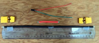
Components of the test rig. 10AWG Black "shunt" wire, 12" to edge of the insulation. The JST sampling leads will be soldered at those points. The male and female XT90s will be soldered to the Black and Red leads, and the rig will be inserted in series with the existing cables to the controller. The CA can sample from either the 1mOhm shunt, or the test rig "shunt".

My controller limits current at 60A, confirmed by the CA max amps through multiple occasions (reading between 59.68 to 59.85, the results are always consistent). I will test max amps between the shunt and test rig, alternating, for 3 samples each. I already know what to expect from the real shunt, 60A. Since both shunts are 1mOhm, I will not change any settings on the CA.

Rig.jpg

The wire was purchased from Amazon and labeled "Bntechgo"
 
Comrade said:
c.) What is the max rshunt mOhm setting in your firmware?
It's much more likely to be the minimum mOhm setting that would be relevant, as I expect the wire will have lower resistance than the typical shunt does, for short lengths. These are the relevant sections from the CAv3 online product info page, with the most likely most relevant section (for ebike11) in bold, and the specific value range underlined:

[ Cal->Range ]
Chooser to select the shunt and current range. The Low range mode is appropriate for ebikes while the High range mode is intended for motorcycles and larger EVs. This affects the allowable shunt range and determines if power is displayed as W or kW.

Lo (W): This mode is intended for systems with shunt sense resistors that are in the 1-9mOhm range. Current measurement resolution is 0.01A and power is shown in watts.

Hi (kW): The high range mode is intended for high current systems that have shunts which are in the 0.1-0.9 mOhm range. All power units are shown in kW instead of W and the current measurement resolution is 0.1A. In addition, all current and power feedback calculations are also affected by the chosen range mode, so that an AGain setting of 50 in low range mode would be equivalent to 500 in the high range.

[ Cal->RShunt ]
This setting calibrates CA current measurement. The CA is only as accurate as the calibration value for the current sense shunt resistor. Most controllers with direct plug-in CA connectors have resistances in the 1.5-6 mOhm range and the Stand Alone CA shunts are 1.00 mOhm. Specifications of high current shunts used in larger EV's are not typically rated by shunt resistance but instead indicate the current draw that causes a 50mV drop. For example, a 200A 50mV shunt has a resistance of 50mV/200A = 0.25mOhm.

[ Cal->Zero Amps ]
This setting calibrates the CA zero current measurement and should be adjusted if the resting current shown in the CA screen is something other than 0.0 amps or watts. The live voltages on the Lo and Hi gain current amplifiers are displayed in real time and should be approximately 2.5V. Pressing the right button sets the 'Zero Amps' offset from the present live amperage measurement. After releasing the button the new Lo and Hi voltage offsets are displayed.

[ Cal->VScale ]
This setting calibrates CA voltage measurement. The factory calibration is about 31V/V using the CA internal voltage divider. If an external divider is employed, then VScale must be adjusted to match the voltage scaling ratio.


Here's a page with some info on wire gauge vs resistance per 1000-feet, including temperature values, etc. It also has links for other size standards, other wire types than copper, etc.
http://www.interfacebus.com/AWG-table-of-different-wire-gauge-resistance.html
These are the copper wire tables from that page:
awg-resistance-data[1].jpg
awg-ohms-per-1000-feet[1].jpg

Something to note: It has been shown in various posts around here that not all wires are actually the AWG value they state in their sale ads (some larger, some smaller), especially from places like aliexpress, amazon, ebay, etc. Same for what comes on controllers, motors, etc.

Another issue is that some wires have been shown to not be copper (or not all-copper), in various ways.

So the resistance stated in a chart like the above may not be what is actually seen on a wire, so it might be more accurate to measure the voltage drop across the wire length for a known current and calculate it's resistance (as you do) than to rely on the chart. :)

It might not make much of a difference to the end-result readings on the Cycle Analyst, but in case readings are significantly different from expectations, it's something to check.
 
E-HP said:
The wire was purchased from Amazon and labeled "Bntechgo"

Do you have a micrometer? Or some digital calipers with at least 0.01mm resolution. I'd measure some strands from that cable, and count total number of strands. Chinese products usually overstate specs as a rule, but cables that I've used have been fine. Doesn't hurt to measure if we are going to have an experiment.

The closer to reality all the input variables are, the better the result of the experiment.
 
Comrade said:
E-HP said:
The wire was purchased from Amazon and labeled "Bntechgo"

Do you have a micrometer? Or some digital calipers with at least 0.01mm resolution. I'd measure some strands from that cable, and count total number of strands. Chinese products usually overstate specs as a rule, but cables that I've used have been fine. Doesn't hurt to measure if we are going to have an experiment.

The closer to reality all the input variables are, the better the result of the experiment.
LOL, OP, now you need a micrometer.
Comrade said:
Theoretical figures for your gauge will be plenty accurate.

I've measured how many feet of wire are left on a big spool just by measuring resistance of a known gauge. It's a very accurate method.
 
Back
Top