Cycle Analyst abnormal readings

amberwolf said:
It's much more likely to be the minimum mOhm setting that would be relevant, as I expect the wire will have lower resistance than the typical shunt does, for short lengths. These are the relevant sections from the CAv3 online product info page, with the most likely most relevant section (for ebike11) in bold, and the specific value range underlined:

The shunts ebikes.ca sells are 0.25 mOhm, 0.5 mOhm and 1 mOhm. That's equivalent to between 3" and 12" of 10 AWG. If the ADC in the Cycle Analyst is able to read higher voltages, from say a 2 mOhm shunt, I'd use 24" of 10 AWG wire, if that length exists, over 12". It should offer a higher resolution of the current reading.
 
E-HP said:
LOL, OP, now you need a micrometer.

This is only to make your experiment, which was done more than 100 years ago and never disputed, more accurate. :lol:
 
Comrade said:
E-HP said:
LOL, OP, now you need a micrometer.

This is only to make your experiment, which was done more than 100 years ago and never disputed, more accurate. :lol:

Why don't you provide the range of accuracy you'd expect due to variations in Chinese wire, and we'll go with that. Or, you can tell the OP which wire (brand/size) to use and what length, which will actually help solve his issue. If it's so simple, why stop short of providing the solutions rather than pointing to Wikipedia? I suspect his conductors are larger than #10 given his current requirements.
 
E-HP said:
Why don't you provide the range of accuracy you'd expect due to variations in Chinese wire, and we'll go with that.

That is impossible. When you are dealing with suppliers like Amazon, nothing is guaranteed to any degree. You could order an 10mm socket which is actually 8mm but is stamped 10mm on it. Anything is possible. :lol:
 
Comrade said:
amberwolf said:
It's much more likely to be the minimum mOhm setting that would be relevant, as I expect the wire will have lower resistance than the typical shunt does, for short lengths. These are the relevant sections from the CAv3 online product info page, with the most likely most relevant section (for ebike11) in bold, and the specific value range underlined:

The shunts ebikes.ca sells are 0.25 mOhm, 0.5 mOhm and 1 mOhm. That's equivalent to between 3" and 12" of 10 AWG. If the ADC in the Cycle Analyst is able to read higher voltages, from say a 2 mOhm shunt, I'd use 24" of 10 AWG wire, if that length exists, over 12". It should offer a higher resolution of the current reading.

Ah, I see your point. :)
 
Comrade said:
E-HP said:
Why don't you provide the range of accuracy you'd expect due to variations in Chinese wire, and we'll go with that.

That is impossible. When you are dealing with suppliers like Amazon, nothing is guaranteed to any degree. You could order an 10mm socket which is actually 8mm but is stamped 10mm on it. Anything is possible. :lol:

Comrade said:
I would just measure the length of the wire accurately and that should be good enough.

For some reason, you made it sound so simple. So what's your educated guess on what the wire shunt will provide? Provide whatever range you are comfortable with, as wide as you want. 30A to 90A?

Here's a link to the exact product, which includes the typical level of information that is provided to the consume. Cross section looks copper.
https://www.amazon.com/gp/product/B01LYEUMC5/ref=ppx_yo_dt_b_search_asin_title?ie=UTF8&psc=1

OP, if this works, you'll be able to do the same thing, since you already have a shunt with a known value. You just need to do your testing at something below the max current, where heat becomes a factor. Two #10s can carry more than a #6, if you use the same wire.
 
E-HP said:
For some reason, you made it sound so simple. So what's your educated guess on what the wire shunt will provide? Provide whatever range you are comfortable with, as wide as you want. 30A to 90A?

Its resistance will be within 1-2% of the the theoretical 0.999 mOhm per foot for tinned stranded 10 AWG. Best guess.

So if you run 50A through that 12" stretch of wire, and the sensing wires are exactly 12" apart, you will see 49.95 mV, and 2.4975 watts of power will be lost as heat. The XT90 connectors themselves will add resistance and drop some amps/volts/watts, so factor that in.

If you have your sensing wires even 3mm off from the 12" spacing, your resistance drops or increases by 1%. That's why using longer sections of wire is easier. If you used 24" spacing but were 3mm off, that would be only 0.5% resistance drop or increase.
 
Comrade said:
E-HP said:
For some reason, you made it sound so simple. So what's your educated guess on what the wire shunt will provide? Provide whatever range you are comfortable with, as wide as you want. 30A to 90A?

Its resistance will be within 1-2% of the the theoretical 0.999 mOhm per foot for tinned stranded 10 AWG. Best guess.

So if you run 50A through that 12" stretch of wire, and the sensing wires are exactly 12" apart, you will see 49.95 mV, and 2.4975 watts of power will be lost as heat. The XT90 connectors themselves will add resistance and drop some amps/volts/watts, so factor that in.

If you have your sensing wires even 3mm off from the 12" spacing, your resistance drops or increases by 1%. That's why using longer sections of wire is easier. If you used 24" spacing but were 3mm off, that would be only 0.5% resistance drop or increase.

You do understand the concept of current flow through a series circuit, correct? The two shunts are in series, and total resistance doesn't change, doesn't matter if you have connectors or not when comparing the two shunts. The sense leads are the same length, and wouldn't present an issue even if they weren't. So based on your description, you feel the reading will be within a few percent.

Soldering up the rig to see if we get to the moon.
 
E-HP said:
The sense leads are the same length, and wouldn't present an issue even if they weren't.

I was not talking about the length of the sensing wires, but the criticality of spacing the sensing wires on the main 10 AWG cable. Since we are dealing with such a short run (12") even a fraction of an inch matters.

E-HP said:
So based on your description, you feel the reading will be within a few percent.

If you used a good ruler to measure the distance between sensing wires, probably even under 1%. :mrgreen:
 
Comrade said:
ebike11 said:
I see...so i just place each wire on the negative main lead spaced out from each other?

Yes. Find points where the sensing wires can be easily attached.

But some thought needs to go into the actual placement. The ADC in the Cycle Analyst has a range. And so does the firmware.

So 3 questions:
a.) How many battery amps max do you expect?
b.) What is the gauge of the wire running from your battery to the controller?
c.) What is the max rshunt mOhm setting in your firmware?

Hi again
I have a pretty large setup with my qs273 motor
Looking at 300A battery amps for sure
Im using 6AWG between controller and battery
Have to check my CA for max rshunt.
At the moment it is set at 0.375
 
ebike11 said:
Looking at 300A battery amps for sure
Im using 6AWG between controller and battery
Have to check my CA for max rshunt.
At the moment it is set at 0.375


So a high strand tinned 6 AWG should be 0.395 mOhm per foot.

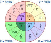
Ohm's law is really simple. You want to know volts drop per foot at 300 amps. What variables do we have? Resistance of wire and amps of current.

ohms_law.gif

So look at the orange volts section. Current x resistance, the 2 variables we have. So 300 x 0.000395 = 0.1185 v = 118.5 mV voltage drop per foot of 6 AWG at 300 amps.

How many feet of 6 AWG do you have between the battery plug and the terminal on the controller?
 
Comrade said:
ebike11 said:
Looking at 300A battery amps for sure
Im using 6AWG between controller and battery
Have to check my CA for max rshunt.
At the moment it is set at 0.375


So a high strand tinned 6 AWG should be 0.395 mOhm per foot.

Ohm's law is really simple. You want to know volts drop per foot at 300 amps. What variables do we have? Resistance of wire and amps of current.

ohms_law.gif

So look at the orange volts section. Current x resistance, the 2 variables we have. So 300 x 0.000395 = 0.1185 v = 118.5 mV voltage drop per foot of 6 AWG at 300 amps.

How many feet of 6 AWG do you have between the battery plug and the terminal on the controller?

Hi
Do i measure the whole length of negative 6awg from controller to battery including the 6awg wire from the main battery connector to the actual pack or
measure the 6awg between where i put the blue a d white cycle analyst jst wires?
 
ebike11 said:
Do i measure the whole length of negative 6awg from controller to battery including the 6awg wire from the main battery connector to the actual pack or
measure the 6awg between where i put the blue a d white cycle analyst jst wires?

I'd measure between the main battery connector and the terminal on the controller. Those are probably the easiest points where current sensing wires from the Cycle Analyst can be attached.
 
Comrade said:
E-HP said:
Soldering up the rig to see if we get to the moon.

So what's the verdict?


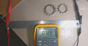
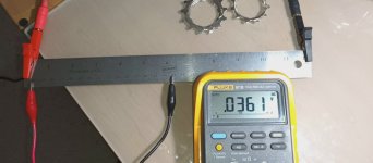
30cm.jpg

15cm.jpg
I may have time later today, but more likely tomorrow, but ready to go. I didn't snap the connector parts together, since I'll desolder and reuse them afterwards. I'll need to tape the in place to avoid shorts.
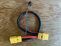
wire shunt.jpg
 
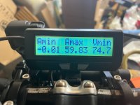
OK, I hooked it up, making no changes to the CA or anything else (set for 1 mOhm shunt). I tried leaving my driveway, but the bike wheelied so hard that I was running behind it after if flipped. I got out on the street and applying throttle as lightly as possible. Same results. The neighbors must have thought I as nuts. I tried no throttle and pedaling back to my garage. Flipped over as soon as PAS kicked in, landing in the neighbor's yard. Hopefully I didn't wreck the plants I landed on. The "shunt" is orders of magnitude off, and the CA is seeing almost no current (voltage) across it, so registering 0W as the max current.
wire shunt amps.jpg

I'm going to have to try it again later, but not sure how to keep the front wheel down to actually get a current reading. OP, I would NOT recommend going this route. Either that, or you'll need a suitcase full of #6 to have the necessary length. My shunt meanwhile registered within a tenth of what it always measures.

real shunt.jpg

I didn't realize I'd be sore after this experiment, otherwise I may have thought twice.
 
Either you have reversed the sensing wires, or the laws of electrical conductivity do not work when you are around. :lol:
 
E-HP said:
OK, I hooked it up, making no changes to the CA or anything else (set for 1 mOhm shunt). I tried leaving my driveway, but the bike wheelied so hard that I was running behind it after if flipped. I got out on the street and applying throttle as lightly as possible. Same results. The neighbors must have thought I as nuts. I tried no throttle and pedaling back to my garage. Flipped over as soon as PAS kicked in, landing in the neighbor's yard. Hopefully I didn't wreck the plants I landed on. The "shunt" is orders of magnitude off, and the CA is seeing almost no current (voltage) across it, so registering 0W as the max current.
wire shunt amps.jpg

I'm going to have to try it again later, but not sure how to keep the front wheel down to actually get a current reading. OP, I would NOT recommend going this route. Either that, or you'll need a suitcase full of #6 to have the necessary length. My shunt meanwhile registered within a tenth of what it always measures.

real shunt.jpg

I didn't realize I'd be sore after this experiment, otherwise I may have thought twice.

Oh sorry to hear about your accident!!
What caused you to flip the bike??
 
Comrade said:
ebike11 said:
Do i measure the whole length of negative 6awg from controller to battery including the 6awg wire from the main battery connector to the actual pack or
measure the 6awg between where i put the blue a d white cycle analyst jst wires?

I'd measure between the main battery connector and the terminal on the controller. Those are probably the easiest points where current sensing wires from the Cycle Analyst can be attached.

Ok i will try this weekend
 
ebike11 said:
E-HP said:
OK, I hooked it up, making no changes to the CA or anything else (set for 1 mOhm shunt). I tried leaving my driveway, but the bike wheelied so hard that I was running behind it after if flipped. I got out on the street and applying throttle as lightly as possible. Same results. The neighbors must have thought I as nuts. I tried no throttle and pedaling back to my garage. Flipped over as soon as PAS kicked in, landing in the neighbor's yard. Hopefully I didn't wreck the plants I landed on. The "shunt" is orders of magnitude off, and the CA is seeing almost no current (voltage) across it, so registering 0W as the max current.
wire shunt amps.jpg

I'm going to have to try it again later, but not sure how to keep the front wheel down to actually get a current reading. OP, I would NOT recommend going this route. Either that, or you'll need a suitcase full of #6 to have the necessary length. My shunt meanwhile registered within a tenth of what it always measures.

real shunt.jpg

I didn't realize I'd be sore after this experiment, otherwise I may have thought twice.

Oh sorry to hear about your accident!!
What caused you to flip the bike??
No current feedback, so the CA isn't taming/controlling the output.

Even though I checked the wiring a few times, I'll swap the orientation and (carefully) test again.
swap.jpg
 
OK, tried it swapped and now have a scrape on my shin from hitting the car bumper when I flipped it. Not interested in testing any more. I'd say it's more than 1% off. This actually proves the idea of why I come to this forum, because real world experience is far superior the academic exercises based on some oversimplified analysis. Bottom line, this idea sucks. YMMV
wire shunt amps reversed.jpg
note: since I was only interested in Amax, I didn't reset in between to zero out Amin.
 
E-HP said:
because real world experience is far superior the academic exercises based on some oversimplified analysis

I'm sorry, but you did not just disprove basic electrical theory by failing to carry out a high school level experiment. :lol:
 
Just curious:

If you put a current thru the wire shunt (such as flipping the bike upside down and just using the throttle to run the motor, what voltage do you measure across it with a voltmeter? (leave your regular shunt in place to feed the CA so it operates as expected).

With the shunt wire not plugged into your system, If you use the meter in continuity mode, do you measure continuity from each of the JST pins to the XT pins on the wire shunt?

I ask these because if there is no voltage across the shunt, or if the CA can't read it because it isn't connected due to wire or connector fault, you'll see the behavior you got.


BTW, the main difference (aside from greater resistance per length of wire) between the manganin shunts commonly used and a "wire shunt" is that the manganin is designed to be more consistent over a wider temperature range than just plain copper wire is.
 
amberwolf said:
Just curious:

If you put a current thru the wire shunt (such as flipping the bike upside down and just using the throttle to run the motor, what voltage do you measure across it with a voltmeter? (leave your regular shunt in place to feed the CA so it operates as expected).
I think this might be difficult to do, but I may be able to wire a voltmeter to the front so I can see, but I suspect it will read 0V.

amberwolf said:
With the shunt wire not plugged into your system, If you use the meter in continuity mode, do you measure continuity from each of the JST pins to the XT pins on the wire shunt?

I did this before installation and then after the test. There's continuity at the JST plug, and the "shunt" measures like a short when my DMM is set to ohms (same as touching the two leads together).

amberwolf said:
I ask these because if there is no voltage across the shunt, or if the CA can't read it because it isn't connected due to wire or connector fault, you'll see the behavior you got.

BTW, the main difference (aside from greater resistance per length of wire) between the manganin shunts commonly used and a "wire shunt" is that the manganin is designed to be more consistent over a wider temperature range than just plain copper wire is.
Do you see anything obvious in how the wire shunt is constructed or inserted into the system? Swapping S+ and S- made no difference, which seems to indicate either a short or open circuit, and it's not open. Could the CA make assumptions when a shunt is outside of the expected range? It doesn't make sense that cheaper wire would have lower resistance.

EDIT: I thought of a less painful way to test this. I can insert this shunt when charging my lipos at 15A or so. That should provide enough current to measure voltage across the shunt wire. I have another shunt lying around that I can place in series for comparison.
 
E-HP said:
I did this before installation and then after the test. There's continuity at the JST plug, and the "shunt" measures like a short when my DMM is set to ohms (same as touching the two leads together).

Ok. At least it should be able to get voltage to the CA.

Another question: Is the JST the wire shunt's JST plugs into on your system the same one your regular shunt uses? I ask this to be sure that the connection path from it is verified working (via your regular shunt).


At only 1milliohm it's expected a typical multimeter will not be able to read it's resistance. It wouldn't be able to read your other shunt's resistance either.

If you like you can test the CA shunt exactly the same way you test this one, and see what voltage you get from it, for comparison, since you can't test either of their resistances directly with the meter you have.


Do you see anything obvious in how the wire shunt is constructed or inserted into the system? Swapping S+ and S- made no difference, which seems to indicate either a short or open circuit, and it's not open. Could the CA make assumptions when a shunt is outside of the expected range? It doesn't make sense that cheaper wire would have lower resistance.
The wire shunt is built (wired) just like the regular CA shunt, excepting that the CA shunt uses a short manganin shunt instead of a longer copper wire shunt.

All the CA does is take the voltage across the wires and do some math based on the value entered for shunt resistance, and the scaling factor based on the hi/low range mode (I think that's all the applicable user-settings) to show the current on screen.

If it reads no voltage, it will show no current.

I don't know what it does if the voltage is so high that it is out of the ADC's range, but if it doesn't damage anything I expect it would just show the maximum possible current. I know that when a CA shunt's connection to the CA is poor, current displayed on screen can be orders of magnitude higher than actual current, as I have had this happen in various situations, usually from water intrusion into the JST).

So anything that has sufficient resistance to have voltage drop across it during current flow can be measured by the CA. If it doesnt' have votlage drop across it, the CA can't measure it.

Wire is wire. It all has a per-length resistance. If it is made correctly (correct metal alloy and conductor cross-section) then it will match the resistance on the industry-standard chart for that particular wire. If it's made cheaply (less conductive alloy or smaller cross-section) it will probably have more resistance than that.


I can insert this shunt when charging my lipos at 15A or so. That should provide enough current to measure voltage across the shunt wire. I have another shunt lying around that I can place in series for comparison.

Any DC current at all would work--if it can be measured by the shunt you already have, it can be measured by any other shunt of similar resistance. The greater the current the easier it is to measure the voltage drop, but it will have some drop even at small currents (how much depends on it's actual resistance).


BTW, when doing this test, since the current is continuous on your charging setup (at least over the span of long enough to make notations of readings), you can measure the voltage across the wire shunt, and use that voltage and the known current measured at the same time elsewhere in the same current path, to calculate the actual resistance of the wire between your shunt's "signal" wires.
 
Back
Top