Cycle Analyst abnormal readings

amberwolf said:
meter you have.
I can insert this shunt when charging my lipos at 15A or so. That should provide enough current to measure voltage across the shunt wire. I have another shunt lying around that I can place in series for comparison.

Any DC current at all would work--if it can be measured by the shunt you already have, it can be measured by any other shunt of similar resistance. The greater the current the easier it is to measure the voltage drop, but it will have some drop even at small currents (how much depends on it's actual resistance).


BTW, when doing this test, since the current is continuous on your charging setup (at least over the span of long enough to make notations of readings), you can measure the voltage across the wire shunt, and use that voltage and the known current measured at the same time elsewhere in the same current path, to calculate the actual resistance of the wire between your shunt's "signal" wires.

Seems like 15A would be enough for a voltage reading (15mV) on my existing shunt. I could also use a 10ft run of #10 to get a better reading on the wire one, but I think I'll just try the rig as is and see if I detect any voltage and go from there, or wait to see if the OP has better luck.

Also, maybe it has to do with the High vs Low range modes for the shunt in the CA settings. Mine is at the default since my shunt is the default value. I didn't change the mode, but if it should be set to Low, maybe not changing it produces unexpected out of range behavior.
 
By the way, this was my little demonstration that resistance and conductivity is a real thing, and is easily predictable to a high degree of accuracy. :lol:

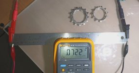
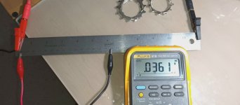
Here is an allegedly stainless steel ruler that is 30.3mm wide by 0.5mm thick. The theoretical resistance for that ruler should be 0.0136634 ohms per 30cm. I've clamped wires that were running 6 amps of current through the ruler, and there was 0.0722v drop at 30cm, and exactly half at 15cm.

This translates to 0.012 ohms at 30 cm. So my real world measurement is only about 12% lower than the theoretical number. Pretty close considering the dodgy placement of probes (current doesn't flow uniformly), and the unknown material, since I doubt it's pure stainless steel.

Comrade said:
 
amberwolf said:
I don't know what it does if the voltage is so high that it is out of the ADC's range, but if it doesn't damage anything I expect it would just show the maximum possible current. I know that when a CA shunt's connection to the CA is poor, current displayed on screen can be orders of magnitude higher than actual current, as I have had this happen in various situations, usually from water intrusion into the JST).
Ok, here's a clue. I put the wire shunt in series while charging my 6S lipos at 12A. Reading at the JST was 44mV, so the "shunt" is shunting, but the shunt resistance is 3.67 mOhm (check my math). This is odd, since that would produce excessively high current readings on the CA, when I'm seeing zero. Both the existing 1.0 mOhm shunt, and the 3.67 mOhm shunt should use the "Lo" range in the shunt calibration settings so it doesn't seem to be a range issue. At least the higher resistance makes more sense than lower for cheap Chinese conductors. Interested to see how the OP's experiment goes.

Another odd observation is that when I got down the hill on flat ground, I decided to take a chance and unplug my shunt to see what would happen. Without the shunt, the take off and acceleration was stronger, but had none of the uncontrollable wheelie behavior as with the wire shunt. Doesn't make logical sense, since I expected not using a shunt would result in a similar behavior as I was getting using the wire shunt, where the current reading as zero, similar to running without the shunt. The midrange was stronger and lifting the front wheel when rolling on the throttle at any speed up to around 17 mph, so that was fun, but scary.
 
E-HP said:
This is odd, since that would produce excessively high current readings on the CA, when I'm seeing zero.

It could be a software "bug", like a buffer overflow, or some routine reading the ADC. Who knows how the CA handles out of range readings on the shunt sense wires.

If you replace your 12" section with 24" and your readings double under the same conditions, you got some real funny wire there. Or any other length of the same 10 AWG. Resistance will be linearly proportional.
 
E-HP, did you abandon this experiment? I do wonder what Amazon sold you. Maybe it’s not pure copper, but some aluminum alloy, or copper clad iron. :roll:
 
Comrade said:
E-HP, did you abandon this experiment? I do wonder what Amazon sold you. Maybe it’s not pure copper, but some aluminum alloy, or copper clad iron. :roll:

I'm done with the experiment, as described. Just waiting to see what happened with the OP's project. Hopefully he is successful.

Plus, my right leg is still a little messed up from landing in the neighbors yard.
 
I guess I have more scientific curiosity than you do. :lol:

E-HP said:
at 12A. Reading at the JST was 44mV, so the "shunt" is shunting, but the shunt resistance is 3.67 mOhm

Any chance you have a small rare earth magnet that you can wave over your DIY shunt?

Iron is 5.8 times less electrically conductive than copper. Your reading suggest that your wire is 3.67 times less conductive than what a copper wire should be. It's not entirely impossible that you have some copper clad iron alloy wire. Is it magnetic to any degree?
 
Comrade said:
I guess I have more scientific curiosity than you do. :lol:

E-HP said:
at 12A. Reading at the JST was 44mV, so the "shunt" is shunting, but the shunt resistance is 3.67 mOhm

Any chance you have a small rare earth magnet that you can wave over your DIY shunt?

Iron is 5.8 times less electrically conductive than copper. Your reading suggest that your wire is 3.67 times less conductive than what a copper wire should be. It's not entirely impossible that you have some copper clad iron alloy wire. Is it magnetic to any degree?

Using a super strong neodymium magnet (can't remove it if it gets stuck on steel/iron), there's no attraction. I read various articles on conductivity of tinned copper, and most say it's as conductive as straight copper, while a small number describe less, depending on the alloy material used to tin it.
 
Weight could also give away something that's not true copper, but that would require removing the jacket and a good scale. The other two variables are your multimeter or the charger amperage. It's either the wire, the multimeter or the charger. At least one of them is so out of spec that the measurement is 3.67x times off from expected. If this was my stuff I would not be able to fall asleep before figuring it out. :lol:
 
Comrade said:
Weight could also give away something that's not true copper, but that would require removing the jacket and a good scale. The other two variables are your multimeter or the charger amperage. It's either the wire, the multimeter or the charger. At least one of them is so out of spec that the measurement is 3.67x times off from expected. If this was my stuff I would not be able to fall asleep before figuring it out. :lol:

No sleep loss here, but if you're having trouble sleeping and don't have a CA, just purchase the wire. You have the equipment to test it. That would be a great contribution to the forum.

I tested to determine whether the concept is practical and a real world alternative. It failed on both counts, using the parameters provided. Nothing was identified as an issue with the test rig before conducting the tests, but I'm hearing a lot of after the fact theories.

It failed, not only for the intended purpose, but it's also 3 times as bulky as my shunt, and couldn't even fit in my connector box, so not practical. Since the OP is picking up the ball and testing with #6, I can wait for his results or yours (if you purchase and test the wire with your metering equipment).

It's the real world experiences people share on this forum that makes it unique. You could google everything else, but it won't always be applicable, relevant, or practical. Fortunately many folks are willing to put up in order to contribute and increase the knowledge bank of the forum. Whether the OP comes back with 3 inches or 3 feet as the length that works, that will be good information, but the latter will likely kick it out of being a practical alternative.
 
E-HP said:
It failed, not only for the intended purpose, but it's also 3 times as bulky as my shunt, and couldn't even fit in my connector box, so not practical.

Never once was it suggested in this thread to make a shunt out of extra wire. You came up with that idea to test. :mrgreen: The original idea is to use existing wire that is running from the battery to the controller, that has a natural resistance. Thus eliminating a standalone shunt as a component, and the extra connections it requires.

E-HP said:
It's the real world experiences people share on this forum that makes it unique.

You didn't have a "real world experience" during this experiment. There is nothing more real world than Ohm's law and well documented conductivity of different materials. The only real world result is that either your wire, multimeter or charger are bum. :lol:
 
Comrade said:
E-HP said:
It failed, not only for the intended purpose, but it's also 3 times as bulky as my shunt, and couldn't even fit in my connector box, so not practical.

Never once was it suggested in this thread to make a shunt out of extra wire. You came up with that idea to test. :mrgreen: The original idea is to use existing wire that is running from the battery to the controller, that has a natural resistance. Thus eliminating a standalone shunt as a component, and the extra connections it requires.

E-HP said:
It's the real world experiences people share on this forum that makes it unique.

You didn't have a "real world experience" during this experiment. There is nothing more real world than Ohm's law and well documented conductivity of different materials. The only real world result is that either your wire, multimeter or charger are bum. :lol:
You are welcome to pick up the ball if you want to satisfy your curiosity. If you just stick to the keyboard, then you can wait for the OP's results; but you have the equipment so you have the option to test yourself.
 
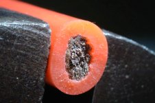
I knew I had it, but I just found a 10 foot length of 10 AWG "highly flexible high strand silicone jacket" wire that I bought from Amazon a while ago.

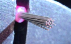
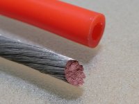
Here's a macro shot of a real tinned copper wire.

tinned_copper.jpg

Here's a non tinned real copper 10 AWG wire.

10_awg_copper.jpg

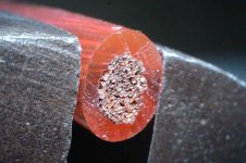
And here is the "highly flexible high strand silicone jacket" from Amazon. :?

10_awg_copper_tinned.jpg

And an extra closeup look. I don't see that copper color. :roll:

10_awg_copper_tinned_closeup.jpg
 
If you'd like to test, you can take some trimmings off the suspect wire and try vinegar or vinegar and salt in a glass jar with them. Over enough time the copper will green up.

IIRC, Miracle-gro mixed with some vinegar on the trimmings should quickly green or blue the copper up.

There are some other ways too, but you'd have to google them as I don't recall. :(
 
amberwolf said:
Over enough time the copper will green up.

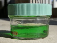
I dropped a 1" clip of the wire into an acid that eats away copper.

acid_jar.jpg

And it did eat it away. So there is copper in the strands. How much and how pure is still up in the air. :lol:

acid_bath.jpg
 
Back
Top