Dual rotor axial flux motor design

Teaser:


Here's an early simulation of the motor BEMF. There are a couple of issues with this simulation, so it's pretty rough. The shape on the Phase A and C waveforms aren't right, so I made a couple of changes to the model to reduce (hopefully eliminate) the edge effects and am re-running (takes some time). I also just checked my math and realized that the units here are off by a factor of 64x. Still, the shape of the phase B waveform looks promising. Correcting the units, I get a Kv of about 174 RPM/V for this geometry. Is that ballpark of what you're trying for? Caveat: this simulation uses N40 magnets, because FEMM doesn't have a built-in model for N42 or N48, so the Kv will end up being lower for either of those strengths.
 
rhitee05 said:
Still, the shape of the phase B waveform looks promising. Correcting the units, I get a Kv of about 174 RPM/V for this geometry. Is that ballpark of what you're trying for? Caveat: this simulation uses N40 magnets, because FEMM doesn't have a built-in model for N42 or N48, so the Kv will end up being lower for either of those strengths.
Thanks Eric. :D

Yes, definitely sinusoidalish. :)

Crikey! I didn't expect to get that close! I was aiming for 150 Kv with N48 magnets :D

That's with 12t? Right?
 
Miles said:
Crikey! I didn't expect to get that close! I was aiming for 150 Kv with N48 magnets :D

That's with 12t? Right?

Yes, this is for two 6t coils on each core, with all 6 pairs for each phase in series. Also using 3 mm thick N40 magnets, with 3 mm thick back iron. I think I figured out how to model N42 or N48 magnets, so I can try those in the next run.
 
Resistance per phase will be something in the order of 25 - 30 milliohms? Rm say 55 milliohms?

An 8t Astro 3210 (weighing about the same) with a similar Kv has an Rm of 80 milliohms.

Looks like I have a fighting chance...... :mrgreen:
 
Hi
I'm Impressed by your motor model, Miles, very interesting, as by your last works, like the beautiful bottom bracket/freewheeling cranck model....

Unfortunately in motors I'm nearly Zero...... :( but just today I've been in a Comsol workshop where they showed some multiphysic simulation models of this motor....not useful for terrestrial vehicles, indeed :mrgreen: , but how not to post a Reaction Sphere Electric Motor on the Sphere?


http://csnej106.csem.ch/detailed/pdf/e-proj-SPHERE.pdf

More here: http://www.comsol.com/papers/9385/

Fascinating thing......just image it applied to CNC..... :shock:

(sorry for the OT :) )

Jules
 
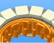
Proposed coil linking system - to avoid blocking the airflow through the gaps between the coils.

The links between the two opposing phase groups can run around above the coils, close against the core heads. Hope there won't be too much stray flux...........

Need to get the three phase wires out somehow, too...... :shock: :mrgreen:
 
Miles/Rhitee05,
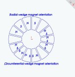
Since different polarizations of magnets are available, one possibility is to have alternating N and S poles on successive magnet faces that are facing the coils. Another possibility is to have the magnet ajoining edges be identical poles so that each successive ajoining edge set is S S or N N. I guess from a FEMM analysis, it would be clear which is the better choice. Can either of you enlighten me which provides the stronger magnetic field for the coils to interact with? I apologize if the better choice is obvious, because it is not obvious to me. I like to learn from others. Thank you in advance for your explaination. A FEMM diagram would be great.
kenkad
 
Hi Ken,

The opposing magnet faces need to be opposite poles, for this topology. If that's what you mean?

What I'm not clear about is whether there would be an advantage in having a slight offset in the alignment, in my case?
 
Miles,
I have attached a JPG of possible magnet orientations. The illustration shows wedge shaped magnets but this is for illustration only because I know that you are using square magnets and I am using vetically oriented rectangular magnets. I assume that you are using the upper magnet orientation. My question was whether the lower left magnet orientation has any value. I would like to see a FEMM magnetic flux intensity plot of the two. This is probably a dumb question, I am just curious what the difference is. Thanks to anyone for the answer.
kenkad
 

Attachments

  • afm rotormagnetorientation.jpg
    afm rotormagnetorientation.jpg
    75 KB · Views: 1,038
Ah! Ok. I see what you mean, now.

I think you mean "axial" polarisation for the top scheme which, yes, is what I'm using.

I think you can only use segmented (circumferential) poles as part of a Halbach array.
 
Yes, wedge magnets with tangential magnetization would only be useful as segments in a Halbach array. Otherwise, they'll just cause a magnetic field around the rotor and never pass through the stator.
 
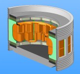
I'm still curious about what holds the cores in place. They will need to take some very high forces.
Air flow between the windings is good, but if the efficiency is high and the copper makes direct contact with the outer housing, I bet it will do a good job of conducting the heat out and you could make it sealed.
 
Miles, let me know when you get done fiddling with the design parameters and I can update the model with a new DXF.

I've been playing with my model trying to get the torque results to a point where I'm happy with them. There are at least two different methods that I'm aware of to calculate forces from a FEA model, and I've been playing with both. So far I'm more confident in the coenergy method, so I'm mostly leaning in that direction. I've also been playing with details like the fineness of the mesh and how many linear positions I have to model to get the results to converge properly. Finally, it's taken me a little time to understand the best ways to construct the model to get (hopefully) decent results. I think I'm getting close to a modeling technique that I'm happy with. Then we can start doing runs for the record, looking at how some geometry changes affect the results, etc. So, I don't really need a "final" model until then.

The big difficulty here is it just takes time to run the model. The current model takes ~30 seconds to run a single point, then I have to look at 100+ points, run each at multiple currents... it adds up. My computer is currently 3 hours into a run and I'm expecting it to finish in about another 3. It's a shame FEMM isn't multi-threaded or this would be much faster... I'll post results later if I'm happy with how they turn out.
 
fechter said:
Air flow between the windings is good, but if the efficiency is high and the copper makes direct contact with the outer housing, I bet it will do a good job of conducting the heat out and you could make it sealed.
Getting enough area of contact with the coils might be tricky? It's one thing getting a nice even coil in 3D graphics... :) You could use thermal paste, as well, I suppose?

I guess the other possibilities are to encapsulate the whole of the stator in resin (leaving the outside turn of coil exposed, as now) or to seal it around the inside of the stator and fill the void with mineral oil.
 
rhitee05 said:
Miles, let me know when you get done fiddling with the design parameters and I can update the model with a new DXF.
Thanks Eric.

So far, I've increased the height of the core by 3mm and increased the effective radius by 0.5mm. I think that should be it, prior to any tweaking that needs to be done based on the FEMM modeling. I'll wait until your first results before doing new DXFs.
 
What flux density do you expect in the smallest cross section?

The magnets look thick. I judge they are capable of producing 1T in the airgap. The smallest cross section looks like 1/3 of the largest cross section. This means the core will have to handle +-3T, if I'm not wrong. Most steels seems to start saturating around 1-1.5T, and are completely saturated at 2-3T. I'm not sure at what flux levels a normal motor is run, but 3T seems like a lot to me. Is this problem?
 
I'm aiming for 1.5T in the constricted part of the core.

The magnets as modelled are 3mm thick (12mm x 12mm).

Core reduces to 3.2mm.

I want to use the minimum amount of iron needed for maximum continuously sustainable current/torque.

If I'm way out, I'll have to adjust the iron : copper ratio; magnet thickness etc.

This relates to my question about oriented-grain steels. I hope I can find out if it's worth trying them.
 
I'm aiming for 1.5T in the constricted part of the core. The magnets as modelled are 3mm thick (12mm x 12mm). Core reduces to 3.2mm.

That means the flux in the airgap will be an average of 1.5T * 3.2 / 12 = 0.4T. It's not needed to use such strong magnets as 3mm neodymium to get 0.4T over gaps of 2 x 1mm or similar. You could maybe use some non-neodymium magnets to make the motor more earth friendly. Or simply use thinner neodymium magnets. With thin airgaps, like 2x0.5mm, it could even be possible to use ceramic magnets.
 
Miles said:
I'm aiming for 1.5T in the constricted part of the core.

The first parameter I'm going to twiddle is to reduce the magnet thickness - right now the model shows ~1.9T peak in the center section of the cores, which is definitely pushing into saturation. Peak densities are even higher in the 2 mm back iron. I'll probably try 2 mm magnet thickness first, then check up/down if necessary. We can check some other possibilities too, like making the cores wider, but that would cost copper fill. Back iron probably needs to be at least 3 mm also, but the only penalty there is a little extra weight.

I was reasonably happy with the last model run, so I think I'm pretty close to being done with that. I'm checking now to see if I can get away with reducing the number of points. I don't have plots handy, but the Kv is up slightly to about 190 RPM/V. BEMF waveform is very similar to the preliminary data I showed earlier. Average torque at 20 A phase current comes to about 0.42 N-m. That's about 40% of what I would expect based on the Kv (Kt should be about 0.05 N-m/A), quite possibly due to saturation in the cores. I haven't attempted to determine that yet. When I start making runs on the final model, I plan to find average torques for a range of currents, with the hope of finding a linear function at lower currents (slope = Kt) then falling off as the cores saturate and eventually leveling off deep into saturation. That should give a reasonable idea of peak and continuous torque capability.

Of course, all of the above will change when I update the model to reflect your dimension changes. Probably not by too much, though.

Miles said:
This relates to my question about oriented-grain steels. I hope I can find out if it's worth trying them.

My reading and limited understanding so far leads me to believe that with the higher-grade grain-oriented steels you're sacrificing the ultimate saturation limit for higher permeability at low fluxes and lower hysteresis losses. So, the net result would probably be a more efficient motor but with slightly lower peak torque capability. Take my opinion with a large grain of salt, though. :)
 
Back
Top