
I have a bike with a green pedel rear hub motor and kt36/48zwsrm-gp01f7 controller. Got it used not working. Said the hub motor is bad. Battery charges, display controller functions, but wiring to the motor controller is questionable as two wire things plug into 3 wire things etc. no signs of burning in the kt controller. Questions: I’d like a pin diagram for the motor connection (round plug). I have a ebike tester off Amazon but it doesn’t support this connector. I have other test equipment available too. Thought I’d verify the status of the motor first if I can. I have no overall wiring diagram or even user manual. Alternative approach : is there a shop in Orange County CA area that is familiar with this setup and maybe sells parts?
You are using an out of date browser. It may not display this or other websites correctly.
You should upgrade or use an alternative browser.
You should upgrade or use an alternative browser.
Green pedel rear hub motor pinout?
- Thread starter Bklein
- Start date
Bklein said:Explain how the key switch works. It is inside the battery receptor housing and no wires come out from the housing except for the two battery lines. So no issue, right?
If by battery receptor housing you mean where the battery plugs into the controller, and the two wires are the battery wires to the controller, then that means the keyswithc would have to be very large and handling the full current of the entire system. That's unusual.
IF you don't mean that you'll need to state exactly what you do mean.
Some controllers require you to pedal (so must have a compatible PAS sensor attached and working) for the throttle to work. Unless the controller documentation tells you, I don't know of a way to know if it is setup this way without testing with and without a compatible PAS attached and functioning.Bklein said:I tried the pedal connection but no change. It’s pin wiring might be wrong though.
That's about the right range, so the throttle is working.The pin wiring on the throttle connection was red/black swapped. Not normally a good thing for downstream things but I checked and throttle voltage still varies as expected like 1v to 3.8v (poor memory).
You usually have to turn the headlight on using the buttons on the display before there is any output on those wires. Different ones use different buttons, but when it's on there's usually an obvious indicator on the display.There is a cable on the old controller for I think just the front headlamp. It has no voltage though so the headlamp doesn’t work. No such cable on the new controller.
The 5v line powers the hall sensors in the motor. The pullups are inside the ocntroller for the signal lines, so when the mtoor is connected to controller you don't need a pullup, but you do need them when testing motor by itself.There is a 5v line in the motor cable. Where is it used? I checked the motor windings by the short/ spin wheel test, and the hall sensors by adding pull-up resistor to 5v and spinning wheel. Control panel registers bike speed from something…
The controller usually usies one of the sensors for speed. In a direct drive motor it's one of the three main sensors. In a geared hubmotor it's a separate sensor still insdie the motor housing.
It's still almost certainly something that is not enableing the controller. What that is will depend on the specific controller design and setup, and could be not getting a valid PAS signal, an alarm system keeping it disabled, a keyswitch line not enabled, the display not switched to the right assist mode, etc.Bklein said:I received the LCD control panel and connected it up. Still no indication of power to the motor.
It did show a throttle issue on the display so I moved the red and black throttle wires in the controller back as they were and this error went away. But still no power to the motor. Jeez, the only thing left IS the motor and it seemed to check good electrically.
At this point I think I will give up on it unless you guys have seen this before and I can fix it. I'm not about to order another hub motor at this point. As hall sensors seemed good and windings passed the short two together at a time test, perhaps something inside is not getting the 5V from the cable. I'd have to take the motor apart to see.
If it's the display mode then changing from mode 0 to one of the other modes should work, some of them only use throttle in the very highest mode (some only allow throttle operation in any mode whne PAS is getting a valid signal from pedalling, some allow throttle in any mode other than 0).
Bklein said:I pulled off the rear wheel and connected 5V/ground to the hub motor and got no hall sensor outputs at all.
I also blew out the throttle receiving circuit in the original controller by forgetting to switch the red/black wires back... :-(
So I decided to take the hub motor apart and see what gives. Then I discovered this motor is not like those on youtube videos.
I don't see how to take it apart at this point. Anyone know how?
I don't think there is anything wrong with the motor. You said all the hall signals tested ok using your own external pullup, and if the phase wires were a problem there would likely be burned smell and melted / blackened windings or phase wires, and the shorted-wires test would not have given typical results.
Dunno about there, but here as long as you can't see it from beyond the bounds of the property line it doesn't matter. My problem is I have a chainlink fence and a corner lot so you can see everything. And I used to have several st bernards so I grew a lot of trees and lantana for shade and to block their view of all the stuff that goes on in the area, to minimize their need to bark at everyhting and to keep neighborhood kids (and other idiots) from teasing them thru the fence. I only have one sb now (jelly bean) because the others all unexpectedly died (which is why i'm still stuck at home on unpaid medical leave the last half year, because it broke me and i'm not really better yet). because I've been so messed up over kirin and yogi dying back in may and june, i haven't been able to do most normal things, and didn't keeep the yard up, and becasue i have no income i didn't water the yard so the grass mostly browned and lantana raggedy. A couple houses in the area went up for sale so the realtors did what they always do and call the city on any imperfect houses/yards in the area, which included mine.Bklein said:No problem, hope they don’t see my garage. I had several projects simultaneously: this bike, a shortwave receiver repair, plant grafting, a dryer repair, and then strong rains… too much stuff in the garage.
so...here i am.
What is a "Star nosepiece"?I lost the star nosepiece for the motor somewhere, not sure if it is really needed.
it's unlikely. that usually gets caused by things that connect the 5v line of the controller to battery voltage.The chip in the old controller is bad (heats up). I think this is due to me misconnecting the throttle.
possible, but unlikely--every one i've tried so far even with mismatched brands has all been fine; sometimes you have to use the self-learn wires on teh c ontroller to teach the right hall/phase combo but even without that the motor would still at lest try to spin or jerk around or make some noise.Now I am suspecting that the motor wiring in the Julett connector of the new controller may be wrong for my motor - like maybe the 5V is not getting to the motor.
Pin 2 of the Julet motor connector and pin 8 may have to be swapped with the new controller. I will make up a cable between motor and new controller to check swapping these. One has slightly higher voltage - should be the 5v source.
I still would like to find the original controller for sale somewhere but no luck so far. New one has misfired throttle and no front light cable. Power connects different too. Rather start out right so if it dies in the future I can get the right replacement. Real sorry to learn of your losses. I lost my dog and parents in the last year. Taking on projects like this keeps me focused although the losses will never be resolved.
I still would like to find the original controller for sale somewhere but no luck so far. New one has misfired throttle and no front light cable. Power connects different too. Rather start out right so if it dies in the future I can get the right replacement. Real sorry to learn of your losses. I lost my dog and parents in the last year. Taking on projects like this keeps me focused although the losses will never be resolved.
this is the pinout i think is normal. it doesn't have numbers on it, but you should be able to match the picture with your actual connector. which signals are swapped on yours?
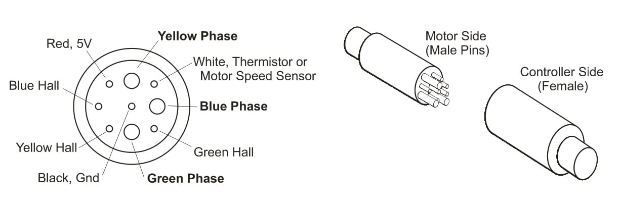
at the controller side you usually see 5v on all of the hall signal lines and the hall 5v power line and the speed sensor wire, if no motor is connected. the 5v hall power line may be slightly higher *or* lower than the signal lines, depending on if they used a diode to protect it or not, but it will be a little different in many cases, while all the others will read the same.
The motor side wont' have any voltage on any lines, unless you apply 5v to the hall power and ground to the ground line, and then it will have basically no voltage on the speed and hall signal lines (unless the motor has internal pullups, but they dont' usually).
I do understand about your dog and parents (lost my mom more than a decade and a half ago, and my dad several years ago; lost so many dogs over the decades I expected by now I"d be used to it but it's worse with every one nowadays, and these last two were the hardest of my whole life).
I will probably have to cut open the existing extension cable to get at the wiring for changes. I tried using the cable from the old controller but it wasn’t working managing all those wires temporarily into the new controller socket.
Swapping white and red. I would think if the others were wrong I’d hear something on power up. I am running out of time returning the controller to Amazon, may order a different one from AliExpress but it would not be returnable…
Swapping white and red. I would think if the others were wrong I’d hear something on power up. I am running out of time returning the controller to Amazon, may order a different one from AliExpress but it would not be returnable…
white is usually the speed sensor wire.
red is usually the 5v wire.
both will read 5v at the controller end because there is a 5v pullup inside the controller on all four signal lines (speedo and the 3 motor halls).
Typically all four signals and the 5v line will be the same 5v, but if only one of them is different, then that one is probably the actual 5v supply. You can test which is 5v supply by disconnecting controller from battery, then measuring with your meter set to 20ohms (2ohms if it has this setting), red lead on the 5v throttle supply wire, black lead to each of the lines that read 5v back when it was powered up. Should read OL for all four signals, but close to zero for the actual 5v wire.
You'd have to physically trace the wires on the motor, or test with your ebike tester or a controller, to determine which ones are which on the motor.
I cut the extension motor cable to access the connections. I put the wheel back on the bike. I discovered the motor windings and hall sensors test good with the tester but only if the wheel moves backwards (bike in reverse). The wheel gear system doesn’t engage if the wheel moves forward so the armature doesn’t move. So the controller wouldn’t get hall transitions if the bike were moved forward. The white speed sensor works regardless of wheel rotation direction.
I tested the hall sensors using the 5v from the controller and one is not right. There is also an intermittent at the input to the motor to this sensor. I can’t fix the motor so I give up - I’ll sell the stuff on Craigslist and move on. Thanks for your help Amberwolf and others.
I tested the hall sensors using the 5v from the controller and one is not right. There is also an intermittent at the input to the motor to this sensor. I can’t fix the motor so I give up - I’ll sell the stuff on Craigslist and move on. Thanks for your help Amberwolf and others.
Similar threads
- Question
- Replies
- 3
- Views
- 119
- Question
- Replies
- 11
- Views
- 891
- Replies
- 3
- Views
- 177
- Replies
- 1
- Views
- 447