Instant Start 18 fet Infineon Boards are here...

Sounds great! Glad to hear that low speed throttle response is not an issue.

I think you will see a pretty big jump in acceleration once you get this past the granny amps setting. :mrgreen:

When are you going to quit playing and get mine wired up?? :roll:
 
This is yours :mrgreen:
I need to burn it in before going to the trouble of sending it to you.
I would be running 60A right now (11:44pm) but the new programming cables and new software wont be here till tomorrow.

I could have soldered the shunt to increase the current but I wanted to keep this one "standard" for you.

This thing is going to knock your socks off Gary :twisted:
Hope you have a motor/bike combo to let it stretch its legs.
I dont want to hear any stories about whimpy Cyclone tests at 2,700W :roll:

-methods
 
wow i cant get over how much the ebike controllers have improved since my little time riding. you guys that do the testing and building are the nuts. Who would of thought we would have 18 fet 100 amp controllers 6 months ago. I miss knuckles .He was so involved also with the controllers
thanks guys
 
yeah, I want one...

just need to build a battery for that controller...

anyone else get problems with their wires getting really hot? I thought it might be the anderson connectors (30A style)

its amazing how inexpensive those controllers are though.

what are the programming options for those controllers?
 
potatonet said:
anyone else get problems with their wires getting really hot? I thought it might be the anderson connectors (30A style)

The 15A, 30A, and 45A all have the same contact patch.
The inline resistance is 500uOhms on 30A Anderson connectors
That is 0.0005 ohms... Which in the real world is Zero.
In comparison, the IRFB4110 has around 3.8mOhms or 0.0038 Ohms of resistance

Your wires are hot because they are too small for the amount of current you are running
The Anderson connector could be the best patch of conductivity that you have :mrgreen:

-methods
 
I did some more testing.
Today I charged it all the way up to 99.7V and bapped the throttle on and off as aggressively as I could.
No smoke :D

Well... Actually there was some smoke.....

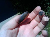
I made Kentucky Fried Fingers again :roll:

Fried.jpg

I got burned (pun intended) switching from 12S4P to 24S2P. I forgot to switch the balance taps :shock:
There is my finger from a few days ago right next to the black ones.

-methods
 
methods said:
I did some more testing.
Today I charged it all the way up to 99.7V and bapped the throttle on and off as aggressively as I could.
No smoke :D

Well... Actually there was some smoke.....

I made Kentucky Fried Fingers again :roll:


I got burned (pun intended) switching from 12S4P to 24S2P. I forgot to switch the balance taps :shock:
There is my finger from a few days ago right next to the black ones.

-methods

Oh.. sorry to hear you were injuried again Method! :?

That's why i really dont want to use dual conector and tap for balancing! What happened to you is exactly what i want to avoid..

But this is good to see you work as hard as this for the E-S community!

Well the results seems interesting.. let us know when you will have 100V 100V or 100V 150A.. and please protect you!! :wink:

We dont want you go to the hospital on the third attempt!

Doc
 
Quit wiping your tear'd up maskara on your fingers, and get to testing at 150amps @100v (15kw).

I want to find out if a pair of these controllers will make it possible to send 30kw to the motors on my bike.

Mmmm! 30kw! thats 40hp!
 
Doc
liveforphysics said:
Quit wiping your tear'd up maskara on your fingers, and get to testing at 150amps @100v (15kw).

I want to find out if a pair of these controllers will make it possible to send 30kw to the motors on my bike.

Mmmm! 30kw! thats 40hp!

wich motor? 8)


Go Methods! test that for us... pics, review... video.. whatever but please post that!!

Doc
 
Yea... the programmers and software did not show up today so I am going to solder the shunt tonight.
I have to do some stuff with the wife for an hour but before bed I will solder a couple legs of the shunt up and see what happens :)
Sorry Gary, looks like your calibration just went out the door.

I looked for 500uOhm shunts today
For 100A I would need a 5W shunt
I would prefer to stick with a 1mOhm shunt to keep the signal to noise in check but I can't seem to find a 10W 0.001 shunt anywhere.

The lower the resistance of that shunt the more the solder imperfections come into play.
If we are going to run this controller at 100V 100A that is 10KW
Even if we burn 10W off on the shunt that is only 0.1% loss.
Very reasonable, assuming the shunt remains stable up to 10W
This would also allow us to stay in the high resolution mode with the CA

So who can find a 10W 0.001 Ohm shunt for <$1 that will solder in plug and play?

-methods
 
methods said:
So who can find a 10W 0.001 Ohm shunt for <$1 that will solder in plug and play?

About 1.25" of 8 AWG nichrome (4 wires in parallel) will do the trick. It shouldn't cost more than a buck, if you can find it somewhere. I'd ask at some appliance repair shops. It WILL get hot...

Hmmm, you might ask this guy for a sample...
 
I have actually got a bunch of nichrome wire, but it is thin for cutting foam.
In this case, I really want something that is plug and play
This first batch of controllers means that I will have to do 30... I will probably end up making 100 more
It is not just the time it takes to install, but worse, the time it takes to calibrate each one.
Thats why I want to hit a large round number that will keep solder blobs in the noise and allow me to just say "0.001 shunt"
Anything I can do to cut time, even if it costs me a little more cash.

Thanks for the tip though!

-methods
 
Ok, I just lowered the shunt resistance from 1.218 mOhms to 514.9 uOhms

Lets see what she does :twisted:

-methods
 
Don't keep us waiting!
 
I've been rewiring my 5304-equipped Townie, adding heavier gauge phase wires, and shortening up the battery wires. This is fully capable of pulling 100A. I have a new 24s5p a123 pack setu[p with all new cells, so 80V/100A should be doable. :)

-- Gary
 
Methy- I had my lady-friend color this for you as a get-well picture for your fingers. Methy's real name is Patrick for those of you that don't know.


methypicture.jpg


Now tell us how it runs at 150amps!
 
I know a couple of babes that are really into Infineon.
They'll be real happy when you get those things going...


You really need to find a source of that wire they use in the shunts.
Another approach I've seen used before is to use copper wire.
About 6.5" of 12ga or 10" of 10ga = 1 mohm. Trim by adjusting the length. Once you find the right length for the desired resistance, it should be fairly reproducible. Current limit will drop as things get hot, which might be a good feature.
 
fechter said:
You really need to find a source of that wire they use in the shunts.

I bet Keywin can get some for us. I will ask.

fechter said:
Another approach I've seen used before is to use copper wire.
About 6.5" of 12ga or 10" of 10ga = 1 mohm. Trim by adjusting the length. Once you find the right length for the desired resistance, it should be fairly reproducible.

Ok, you guys are right... I need to give it a try.
Maybe I can do something to control the solder wicking.
Maybe solid core wire

fechter said:
Current limit will drop as things get hot, which might be a good feature.

This sounds like a great feature!
If we did this though, we would need a different shunt to track AH with.
I am beginning to think we should use one shunt for the controllers and a different shut for the CA.

-methods
 
90V @ 60A = :shock: WTF !?!

Motor: Front 9x7 9C in a 26" rim
Battery: 100V to start, 90V under load
Current: Cont. ~60A, Peak 149A
Power: >5KW

OMG!!!
9C @ 90V and 60A is awesome!
I can roast off the front tire at any speed under 30mph
I did one blast all the way down my street and every pump of the pedals makes the front tire roast

I rode the 1.2miles to work (which read 4 miles after burnouts :wink: ) + 4 miles of looping side-tracks
Only bursts of WOT, 55Ah/mile
2 or 3 one minute rips at WOT. (EDIT: Make that 2 or 3 20 second bursts... Time warp :roll: )
Temperature ~60F
Motor = warm
Controller = warm on the fet side, cool on the wire side

So I contacted Keywin to talk about the software.
He is still working out the bugs
He was quite disturbed that we are going to run 100A. I think I made him go cross eyed :D

To be fair, he is not aware of all the modifications i am making to the controller.
The 4110's are only part of the story.
Thick wires and wicking up the solder tracks is also just another part piece of the puzzle
Making sure that everything is clean, well secured, heat sinked is very important
Taking the time to closely inspect the traces with a jewelers loop is critical. Just a tiny little hair of copper (invisible to the human eye) can start the avalanche.

There is no doubt that this controller is going to be able to handle >>100A
My only concern now is if the caps and fets can handle the kickback at near 100V
I am confident that if we keep voltages below 90V it will be cool.

After work today I will solder the shunt down to ~300uOhms and give it the ol' 90A run.
No sense beating around the bush, I will start out at 100.8V

-methods

P.S. Running a pair of 9C motors at 90V 60A will absolutely piss all over a single 5305. This single 9C was not quite on par with, but getting very close to, my 5305.
 
I am considering "going big"

Perhaps we should step up to a true variable regulator, proper shunt, and 150V caps.
If we do this, I think we can rate the controller at 100V 100A conservatively instead of hesitantly.
These 100V caps really are cutting it close when running 24S lipo....

Keywin would be glad to eliminate the caps from the build and the cost per unit would certainly reflect this.

I think this is going to boil down to whether we want to build a controller for the masses or a controller for the insane.
The price of the caps wont be that much but the labor keeps increasing.

how many other people out there are actually running 24S lipo or equ?
Probably only 5 or 6 of us
I bet most people are running more like 70 - 80V tops.
If this is the case, we are set as is.

-methods
 
Horray for Methy!

Now solder that shunt up :) There is still smoke in that motor that needs to be let out!
 
greasypants said:
My 2s30p psi pack is 109 volts fresh off the charger but quickly drops to 100 volts.

30S2P right :D

I am thinking that I am gong to produce a special version for the lunatic fringe like you and I :wink:

Out of curiosity, would you rather pay more for a completed controller or would you enjoy the challenge of building a kit?

-methods
 
Thanks Methods for your first REAL review!

you said 9C 90V 60A... F R O N T ?????? what kind of fork/dropout/troque arm do you have!!???
( tis time please monitor the temp inside!! dont burn it like the 5305!! in overload!)

At 90-100V, caps MUST be 160V rated.. that was previously detailed over past years with lowell and xyter's setup and fechter.

the problem is that to get the uF needed at that current we should double the capacity and work with 160V.. so the caps are bikker...

The trick would be to put many low uf value in parallel over the rails.. that would be more stable for capacitance and inductance for the mosfet.

Also a great upgrade would be to use true MICA instead of that grey "rubber".. the heat transfer is alot better! and would make the jonction work cooler... giving higher current capability!

By my side i would suggest to buy 160V caps in large quantity as for the 4110... the 4110 order should be done with the 160V caps too.

As for the the current increase.. why do you solder the shunt??.. it cold be simpler to just modify the resistor valoe near the comparator near the sense trace from that shunt right?? the crystalyte analog controlelr had that smt resistor.. I added a pot.. it is simple, fast, adjustable!.. maybe that can be done on the infineon and that just overide or... offset the current value of the programed value..

Doc
 
Back
Top