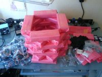
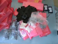
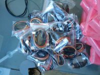
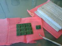
Instant Start 18 fet Infineon Boards are here...

greasypants said:
My 2s30p psi pack is 109 volts fresh off the charger but quickly drops to 100 volts.


Do you operate at 109V fresh using the 4110 mosfets on the controller???

I know only another person here who did that without blowing them...

I thought doing that with 30s on my drag setup and to remove the few surface charge 6-7 volts using a large dummy load before to connecting the battery on it..
 
methods said:
I am considering "going big"

Perhaps we should step up to a true variable regulator, proper shunt, and 150V caps.
If we do this, I think we can rate the controller at 100V 100A conservatively instead of hesitantly.
These 100V caps really are cutting it close when running 24S lipo....

Keywin would be glad to eliminate the caps from the build and the cost per unit would certainly reflect this.

I think this is going to boil down to whether we want to build a controller for the masses or a controller for the insane.
The price of the caps wont be that much but the labor keeps increasing.

how many other people out there are actually running 24S lipo or equ?
Probably only 5 or 6 of us
I bet most people are running more like 70 - 80V tops.
If this is the case, we are set as is.

-methods

I'm running 32 cell thundersky cells and I'm as much as 115 hot off the charger and 106 to 104 no load after the surface charge is gone. I might be interested in quantity if they can be made to work with the MHM-602 motor on a motorcycle build at the voltage I'm using. This may be beyond the scope of what your trying to do right now but I hope you would consider it.

Mark
 
Doctorbass said:
Thanks Methods for your first REAL review!

you said 9C 90V 60A... F R O N T ?????? what kind of fork/dropout/troque arm do you have!!???
( tis time please monitor the temp inside!! dont burn it like the 5305!! in overload!)

No torque arms. All I have is tight bolts and a wrench on the right side bolt hose clamped to the fork.
The bolt can not turn.
This is a walmart bike though, total death trap. Just using it for a little testing.
Yea, yea... I know. Dont forget, I am an "over the bars" veteran.


Doctorbass said:
At 90-100V, caps MUST be 160V rated.. that was previously detailed over past years with lowell and xyter's setup and fechter.
the problem is that to get the uF needed at that current we should double the capacity and work with 160V.. so the caps are bikker...
The trick would be to put many low uf value in parallel over the rails.. that would be more stable for capacitance and inductance for the mosfet.

That is not necessarily an absolute fact.
I agree that it would be wise to have high voltage caps and we may go that direction for the higher voltage boards (or all boards)
How much capacitance was on the boards you guys were testing? These already have like 5mF.
I think it greatly depends on the quality (and margin) of the capacitors and the design of the board.
Some spike suppressing diodes on the main power rail may be another answer. Did anyone investigate this?


Doctorbass said:
Also a great upgrade would be to use true MICA instead of that grey "rubber".. the heat transfer is alot better! and would make the jonction work cooler... giving higher current capability!
By my side i would suggest to buy 160V caps in large quantity as for the 4110... the 4110 order should be done with the 160V caps too.

I dont think we will create enough heat to necessitate that much cooling overkill. Most people will not even be capable of running 100A cont. Even if they do our RdsOn is so low that I dont think it will be an issue. Again, I appreciate the ideas though and if we get "that serious" we will certainly consult you for the crazy ideas!

Doctorbass said:
As for the the current increase.. why do you solder the shunt??.. it cold be simpler to just modify the resistor valoe near the comparator near the sense trace from that shunt right?? the crystalyte analog controlelr had that smt resistor.. I added a pot.. it is simple, fast, adjustable!.. maybe that can be done on the infineon and that just overide or... offset the current value of the programed value..

Doc

The shunt is 1.218mOhms in stock form
At 100A that is way over 10W
I think it is wise to lower the shunt resistance to keep the temperature under control.
It is also a hell of a lot easier to glob solder on a shunt than to try to lift surface mount parts (if there are any to lift)
Remember that these are programmable. We dont need potentiometers. Only the parameter software :D
The only reason i soldered these shunts was because we dont have the software yet.

Thanks for the tips doc!
If we get into trouble I am sure that some of that sound advice will find its way into the design.

-methods
 
markcycle said:
I'm running 32 cell thundersky cells and I'm as much as 115 hot off the charger and 106 to 104 no load after the surface charge is gone. I might be interested in quantity if they can be made to work with the MHM-602 motor on a motorcycle build at the voltage I'm using. This may be beyond the scope of what your trying to do right now but I hope you would consider it.

Mark

I cant speak as to whether this controller can drive your motor (it should do most brushless motors with 60 or 120 degree halls) but I suspect we could build you a prototype to test it out.
Something like that would clearly require better capacitors, more attention to detail on the power traces, better cooling, etc.

Sounds like Doc may have the ticket for your build!
I should send him a controller and he can prep it for you :twisted:

-methods
 
Most capacitor failures I've seen are due to heating (caused by high ripple current and poor ESR) or by vibration, not from excessive voltage.
methods said:
I am considering "going big"

-methods
Infineon girls 1a.jpg
 
I agree...quality and longevity are important enough to warrant paying more for a unit.

--Ryan
 
it may be worthwhile to reconsider the placement of the caps also and the type of conductor from the battery perhaps a ribbon rather than a round conductor, and mount the caps very close to the main S/D busses to reduce the total inductance. keywin added some at each end, but it may behoove you to consider having the case open to test out the idea of using large caps soldered directly onto the S/D busses from underneath, perhaps having them sticking out the bottom, normal to the pcb. the legs should be as short as possible, not sure if the voltage rating will matter that much then.

also the idea of using diodes on the input power requires that the diode be able to recover if it goes into avalanche, and is there a length of time it takes to recover? is that too short for the inductive pulses at the speed of the processor? but zeners do that all the time i guess. maybe adding more resistance behind the zener would help a lot.

they do that to the regen goldenmotor controller. between the S/D busses, on the underside of the pcb, but there they do it because it allows the regen spikes to short out above a certain level to protect the caps. that board has 63V caps so they chose 62V zeners and latched the busses at 63V. my theory is that they did the regen that way because they could not make the 100V caps fit, and they already had the 36V pcb's made and rather than build new ones with larger caps, they hung the zeners across the S/D of the FETs, with a .2ohm 3W power resistor to absorb the energy, they all burned up.
 
This is really good feedback
(especially the pictures from Fechter...)

It is clear to me now that we need to go two directions.

One direction will be low cost - high power
We will de-rate the boards a little and sell them to quasi normal people.
It will still be a tremendous value and the boards will handle way more power than most people can utilize.

Direction two will be supercharged, double-gangster, over the top, insane, double-blaster mode. :mrgreen:
This will probably be more for just you guys, a kit sort of thing.
I like the idea of huge caps poking out of the case, gnarly screw down shunts, retarded over-kill....

The irony is... I bet that the "normal build" I do will be able to handle 100V 100A cont. (with 200A burst) just fine. :wink:

-methods
 
I charged it up to 100.8V again and ripped back to work from lunch.
I cant get over how this thing will break the tire loose at almost any speed.
Makes for one hell of a show!

On my way out to lunch one of the managers (who had heard a story about me doing burnouts with duct-tape on my tires for a "side show") made the universal "REV IT UP" sign with his wrist. :D
I pulled up next to him, wrapped the throttle around and smoked about 1/8" of my tire off with a big stupid smile on my face.
I could tell he was embarrassed and worried that I would hurt myself causing some sort of "work incident" lol...

First thing when I get home tonight I am bumping that shunt down again.
It has been a while since I have had the "ebike grin"... It has been a long trail of sadness since I blew the X5, blew the Cyclone, blew my 10Ah battery pack.....

Ahhhhh...... Making progress again!

-methods
 
Thanks for the correction Methods, my packs is 30s2p.

I would probably prefer to build up a kit myself as I have some good quality 8 gauge wire and 75amp Andersons for the battery connections and I have 10 gauge wire for the motor connections so I can customize the length to fit my bike but a completed controller is tempting.

I have not connected a controller to the bike at 109 volts fresh of the charger yet as I presently do not have a functioning controller. I have a blown digital crystalyte controller with 4110's and a blown analog crytalyte controller with 4110's. I am in the process of repairing the analog controller as it was very reliable on my previous bike at 102 volts of the charger until some water leaked in.( that was with nimh cells so the voltage sagged a lot under load and was quickly down to the mid 80's) I known Lowell said the 4110's should be ok up to 112 volts but I have never tried it. My 30s2p pack drops down to 102 volts after 30 minutes to an hour off the charger, or I can turn on my 85 watt head lights for a few minutes to burn of the surface charge.
 
Since Fechter was nice enough to try to offer up a couple of his Infineon Girls, I thought it only right that I show him the kind of woman I really would prefer...

Behold -> The perfect woman

Perfect_Woman_002.jpg


ok, obviously I just got the second shipment of controllers and I am a little excited.
Here is some more controller pron.

Perfect_Woman_003.jpg
Perfect_Woman_006.jpg
Perfect_Woman_007.jpg

Now I am off to solder that shunt down to about 7 nano-ohms...

-methods
 
Oh, I forgot that I ordered these.

Sensorless_001.jpg

Sensorless boards!
I have not been following up on the threads.
Wasn't there something about a max frequency on these that was causing people to have to only run up to 70% throttle or something?
I recall something about hooking to a pin in the controller?

Anyhow, personally think sensorless sucks (but Patrick... tell us how you really feel... lol)
I know you characters love this stuff so let me know who wants one and I will ship them out.

I know that Luke gets one and Gary gets one.
Who else?

-methods
 
methods said:
Since Fechter was nice enough to try to offer up a couple of his Infineon Girls, I thought it only right that I show him the kind of woman I really would prefer...

Behold -> The perfect woman

View attachment 3


ok, obviously I just got the second shipment of controllers and I am a little excited.
Here is some more controller pron.

View attachment 2
View attachment 1


Now I am off to solder that shunt down to about 7 nano-ohms...

-methods

lol!.. We now have a mascote for infineon :mrgreen:

Please Methods.. could you use SUPRA shunt?

ln2dem20.jpg


or big HV capacitor?:
lethal.jpg


:mrgreen: :mrgreen:

Doc

Thanks for the update!!
 
Methods ... I am INSPIRED!

Love the burnt fingers.
OUCH! but ... LOL ...
I'M LOVING IT! :D

file.php


GREAT to see you INTERFACING with Keywin!

I have been waiting for SOMEONE to do EXACTLY this. IT AIN'T EASY!

But you are doing Very Very Good!

GOOD JOB!

Kudos!

-Knuckles

8)
 
I want 5 of them. I want to make the worlds fastest RC boat, and I'm thinking I need 2 for my boat, 2 for my bike, and 1 for a spare.

-Luke

PS: I'm going to make a 20-30bhp electric RC boat that is tiny and light. :)
 
I have set the shunt resistance to 231.4 uOhms
This effectively eliminates the current limit.
It will be >120A and probably closer to 150A

I would like for everyone to take a moment on the toilet this evening and play a short version of taps with their mouth trumpet (or whatever trumpet you have available) in loving memory of my 9C (which has only gone just a short 20 miles or so) and the first Instant Start controller to leave my lab (otherwise known as "The Meth Lab"). Murphy's law states that if we morn their loss they will live forever.

Luke - Special price for you, only $300 + $90 shipping (each, no combined shipping plus all applicable sales tax)

Knuckles - thanks. Special sale price available to you too. :wink:

-methods
 
methods said:
Oh, I forgot that I ordered these.

file.php


Sensorless boards!
I have not been following up on the threads.
Wasn't there something about a max frequency on these that was causing people to have to only run up to 70% throttle or something?
I recall something about hooking to a pin in the controller?

Anyhow, personally think sensorless sucks (but Patrick... tell us how you really feel... lol)
I know you characters love this stuff so let me know who wants one and I will ship them out.

I know that Luke gets one and Gary gets one.
Who else?

-methods

hi
I did not find the fault with the sensorless boards it was observed while I was off the road. what I did do when I finally got a sensorless board to check out was to find the find the point of the fault , the reason is still beyond me as simmilar to you methods I don't like the sensorless fix, here were my results.

I was using a 12 fet controller fitted with a sensorless board and a puma motor(later confirmed with a kollmorgon)
I started at 48v
I observed that when the throttle went past approx. 75% the motor started to do strange things ( jumping and stuttering it was setup on a bench)
thinking this might be voltage I changed to 36v
the same results were observed whenthe throttle got to 75% so it cannot be the voltage
to prouve my theory I changed to 72v same results as before.

I disabled the sensorless board left it in place and started doing other tests.
I was going through the pads first testing for a voltage then if there was none shorting to ground to see what the results would be, I found a few 5v pads that LEDs probably connect to but that is for another time, I finally came on one marked SLA i connected this to ground and found this was a fixed throttle limitter, with all the advanced features of this controller that seems strange why do it, software would be so much better.
then I had a thought the speed mesured was about the same as the speed at which the sensorless went wrong so i enabled the sensorless board with SLA grounded and gunned the throttle, not a glitch in sight the motor ran as smooth as silk.

I think that SLA must stand for SensorLess Adaptor

Now I was testing with geared motors much higher reving than direct drive, I thought it could be the rpm of the motor that was the problem but I was able to get much higher smooth revs running at 72 v than at 36v but the problem was always at approx 75% throttle if you mesure the throttle signel I thing you will find that it is about 3v.
I only just got a DD motor and it came in a rim it will not fit in my bench test unit so I can't test DD but I fear that may not work either, i hope I am wrong.

Geoff
 
So, if you ground that SLA pin, it runs fine on the sensorless module?

I'm needing to support 12,000-13,000rpm on a 12 pole motor. Do you know if your tests were in a similar electrical RPM range? Did you ever try it under load?
 
liveforphysics said:
So, if you ground that SLA pin, it runs fine on the sensorless module?

I'm needing to support 12,000-13,000rpm on a 12 pole motor. Do you know if your tests were in a similar electrical RPM range? Did you ever try it under load?

hi
thats correct grond the SLA pin it is marked on the 18 fet board I looked.
as for tests none of my motors spin that high, I have still not tested at load the controller with the board on it popcorned some of its fets in testing, I have been working solid in the UK on other stuff no time to build a bike to test with I was off the road because my ride was stolen finally converted a little folding bike with 16" wheels and a bafang designed for a 26" wheel,I'm running at 36v so speed is only 9 mph but at least it gets me from A to B on the train as well I am just waiting for parts to inprove speed.
this is no good to do tests on though, im converting a moutain bike for that.

Geoff
 
methods said:
Oh, I forgot that I ordered these.


Sensorless boards!


-methods

I like your choice in women :wink:

I always wanted to play with one of those sensorless boards. If it works with RC motors, it could be a hot combination. Hall sensors are such a PITA anyway. I'm not sure if any of my controllers are compatible with it though. I wonder if one would work with an old Xlyte analog controller?

Knuckles: nice to see you back. Yes, this is a great step forward. The only thing I worry about is when the first batch is all sold, the next batch will be a completely different design and a bunch of stuff will need to be reverse engineered again.

I'd still suggest working out an analog current limit adjustment for those high-amp versions. I find having an adjustable limit to be very useful (something you can tweak while riding).
 
Knuckles is alive! Who'd a thunk it?

Well, methods, you have proven that if one of the ES elite goes far enough "over the top" (and trust me, you are there :wink: ) even our most "derelict" contributors will chime in. Good job!
 
Back
Top