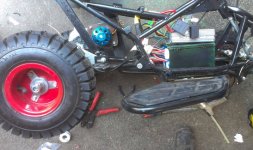
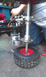
its now a e-motorcycle

wish i had a frame like yours...

Im having a bit of trouble fitting my hpm, iv had to grind some of the orignal aluminum frame down to fit the electric motor
 
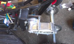
its been a lot longer than I had hoped but I managed to do a little to the mount:
View attachment 3
twin_2.jpg

I have been doing a lot of other ev stuff here are some pics of another project:

quad1.jpg
quad2.jpg
quad3.jpg
 
So how is the pocket bike tranny working out? did you get the clutch working? All I could do with one of those is relase 1800w of heat with the clutch stalled...
 
Neat. I'm looking forward to how this double motor setup works, as I have plans to fit two 80-100 motors to a common shaft for my motorcycle build. My layout would be pretty similar to this, with the motors tucked up where the old airbox was and the layshaft just in front of the swing arm bearings.
 
bzhwindtalker said:
So how is the pocket bike tranny working out? did you get the clutch working? All I could do with one of those is relase 1800w of heat with the clutch stalled...

its only running at 600w at the mo, but the first clutch we tried ( it was a cheap one ) didnt last 5mins it got very hot very quickly so we replaced it with a racing clutch , yes this is lasting so far and works a treat, we removed the springs but its still not quite enough even at only 600W so I think when its upto around 3.5kw its going to be a big problem with wasted heat. As it stands ( only at 600W ) its going to go up against a tuned 100cc mini quad on a Kart track ( tomorrow ) which should be fun If it survives. I have asked the peeps to take some video as its is going to be close ( its a very short indoor track) even that the e-quad is only geared for around 20mph and the tuned quad will do around 50mph but the tuned quad is a nightmare to control and flips very easy where as the e-quad handles much better and accelerates faster upto its max speed.

Jeremy Harris said:
Neat. I'm looking forward to how this double motor setup works, as I have plans to fit two 80-100 motors to a common shaft for my motorcycle build. My layout would be pretty similar to this, with the motors tucked up where the old airbox was and the layshaft just in front of the swing arm bearings.

Sounds like you are planning more or less exactly the same setup as this ( except the common shaft ) I have opted for 2 controllers with these motors as I know how the motors behave and don't eat controllers for a past time, If this setup works out I have the option to swap out the 63mm motors and install 80mm motors and in theory, if I make a different set of motor plates I can actually fit 4 x 80mm motors. I will be watching yours to see how you get on with the common shaft setup and how you get on with a controller.
 
This is the gas mini quad that it will be up against :mrgreen: :

souped up mini quad.jpg
souped up mini quad_1.jpg

Its only for fun so I am not hoping for a big upset ( not yet anyway :D )
 
update:
I have put the 2 motors onto the bike and rode it up and down a bit :roll: at the moment its limited to 5 kw and all I can say is wow what a difference just a extra 1.5kw can make . I will do some proper testing when I get the chance. @JH the 2 motor config works very well and shares the heat/load well, im not totally sure that 2x80-100 are needed for a small road going bike but I spose it depends what you want your top speed to be.
 
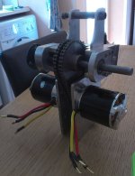
here is a pic of the setup before I installed it on the bike, each motor draws 2.3A no load @50v but I was very supprised to find that even if one motor is disconnected completey and just power one motor the no load current is still around 4.6A ( I didnt expect that ) so I may install a one way clutch bearing on one of the sprockets so I can optionally turn one motor off once the bike is upto speed to help save a little bit of battery or maybe even make it auto shut off dependent on current draw, when the current drops down to around 40A @ wot then one motor will auto shut down :?: .
 
I took a small bit of vid of the bike being ridden by my son-in-law and posted it up on youtube if anyone is interested

[youtube]EQdjFkYTJZ8[/youtube]

There are a few minor technical problems to sort out with it but I think its a very good setup.. even if I do say so myself :mrgreen: , the current limit is only set for 5kw at the mo.
 
Thought I would share one of my solutions for a fuse holder/antispark connection, each fuse can be 30A so its quite configurable so 90A per total fuse, a pullable link could be used for quick disconnect. I will be using 2 of them as I am running 2 controllers.
fuseholder_antispark1.jpg
fuseholder_antispark2.jpg
 
gwhy! said:
Thought I would share one of my solutions for a fuse holder/antispark connection, each fuse can be 30A so its quite configurable so 90A per total fuse, a pullable link could be used for quick disconnect. I will be using 2 of them as I am running 2 controllers.

Any pics available to see the internals of wiring/fuse connections underneath the shrink wrap?

Which exact fuse parts?

Anti-spark is done with what parts for connection?

Thanks. :D

im not totally sure that 2x80-100 are needed for a small road going bike but I spose it depends what you want your top speed to be.

What about Dual 6374 ? :twisted:
 
Here is a diagram of the internals. the fuse holders are stackable, and the value of the resistor (3W) was selected to gently pre-charge the caps in the controller and not produce to much heat if the link was not connected.
fuseholder_antispark_.jpg
stackable fuse holder.jpg
 
gwhy! said:
Here is a diagram of the internals. the fuse holders are stackable, and the value of the resistor (3W) was selected to gently pre-charge the caps in the controller and not produce to much heat if the link was not connected.

Thanks for the fuse pics/info. :)

im not totally sure that 2x80-100 are needed for a small road going bike but I spose it depends what you want your top speed to be.

What about Dual 6374 ? :twisted:

Any advantages going with Dual 6374 smaller motors vs two 80-100s???
 
I have opted for the smaller motors as I know them very well and how they behave with the controllers. I have a set of 80-100 that I could put on to the bike but at the moment there is more than enough power ( with a bit to spare ) with just the 2 smaller motors so as long as I can keep this sort of torque performance after I regear the top speed then I will be very happy, at the moment its geared for only a top speed of 22mph while 22 if fine for most trials sections you sometimes need around 28mph for very steep, long hill climbs, so time will tell, the other advantage of the smaller motors is the no load current is only a tad over 5A for both motors, and if I were using the bigger motors this will be more like 11-12A, I know that for normal road riding with the 2 small motors it would be for around 40-50mph and still have very good acceleration on a bike that is around 50-60kg
 
...the other advantage of the smaller motors is the no load current is only a tad over 5A for both motors, and if I were using the bigger motors this will be more like 11-12A...

Why is the no-load current so much higher than what is advertised for each motor??? Or, is that accurate as spec'd ?

Thanks. :)
 
deVries said:
...the other advantage of the smaller motors is the no load current is only a tad over 5A for both motors, and if I were using the bigger motors this will be more like 11-12A...

Why is the no-load current so much higher than what is advertised for each motor??? Or, is that accurate as spec'd ?

Thanks. :)

They are crafty with the advertising you need to look at what voltage they are measuring the noload current at :( , i think the small motors that I have are avertised with a 1.9A noload current but this is at 10s and Im running them on 12s hence way the aprox 2.3A noload for each motor and the extra little bit of current is because I measured the current with the motors coupled together through the jackshaft .
 
I have posted a small vid of the quad that I have been playing around with, it went up against the ice quad on a kart track but the ice quad picked up any ground it lost in the twistys on the straights :) , so now we are looking at upping the power and top speed, and this little vid is just the initial upping the current to 40A ( still another 40A to try )
[youtube]CqdEV3zOdaU[/youtube]

The clutch is holding up very well,,, so far.
 
update on the e-motorcycle:
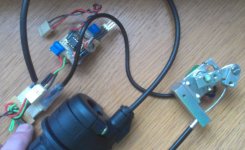
Due to the resolution of the throttle for fine motor control at very low speeds I needed away of adjusting the resolution on the fly as I was riding, so I came up with a e-clutch lever and the interface for the controller, it all appears to work well on the bench :D , so I just got to get it on the bike to test.

e-clutch_1.jpg
 
would love to see your circuit drawings for it or is this gonna be proprietary? why did you put the extra 3 pin plug in parallel? is that for monitoring it while working on it?
 
dnmun said:
would love to see your circuit drawings for it or is this gonna be proprietary? why did you put the extra 3 pin plug in parallel? is that for monitoring it while working on it?

The small 3pin plug is for programming the chip. I could have done it with op amps but I find using the 8pin picaxe chips to be a bit easier ( and I have lots of the chips :D ), one of the pots is for setting the offset for the controller, so no matter what is happening with the clutch part the throttle will always start driving the motor from the same spot on the throttle and the second pot is to set the throw of the throttle so the full twist of the throttle is used so there is no wasted resolution.
 
neato. i don't know picaxe, but just bot some junk that has a pic16... chip on it to control the board, so that may be the processor module. i should read more. is there a good wiki spot?

so instead of the resistor in the base of the throttle line the picaxe will have an output equal to that offset, and then be able to provide the full 4.7V to the controller without shutting off the controller from high voltage default protection. and you just use the 5V supply for the picaxe.
 
dnmun said:
neato. i don't know picaxe, but just bot some junk that has a pic16... chip on it to control the board, so that may be the processor module. i should read more. is there a good wiki spot?

so instead of the resistor in the base of the throttle line the picaxe will have an output equal to that offset, and then be able to provide the full 4.7V to the controller without shutting off the controller from high voltage default protection. and you just use the 5V supply for the picaxe.

that's the plan,

http://www.picaxe.com/What-is-PICAXE/
 
I managed to get it on the bike and test it for about 2mins :lol: , it is very strange to ride but it works just like a real clutch !!. its going to take a lot of getting used to as there is no engine noise to gauge clutch position :| , with the clutch lever pulled fully it sets the throttle resolution to around 1v for a full twist this is a bit of a pain as it still creeps a little ( think I need to install a micoswitch to completely disengage the throttle ) ,and when the clutch lever is fully out you can still stop with out stalling (unlike a gas bike ) which makes it feel a bit odd,, Hopefully I will get some longer peg time soon to really see if it really makes a big difference to control ( and to get used to it :mrgreen: ), but the best bit is that you can have the throttle at max with the clutch pulled in then with just a slight movement from the clutch finger you can dump full throttle power into the motor for that explosive (looping) power :mrgreen:
 
subscribed
 
Back
Top