KONA Entourage Build Thread - middrive (pic heavy)

updates come slow, as this is really a lot of work. designing the battery box took longer than i wish it had. i changed the design at least four times. and each time i had to remake the whole box glued together. a lot of cutting cardboard and gluing it together.

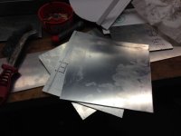
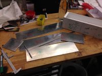
now that the final design is done i started cutting the aluminium sheet.
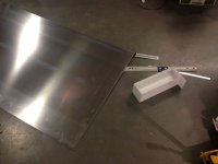
2014-03-06 at 17.35.01.jpg

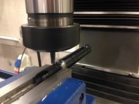
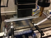
some pieces cut with the saw. next thing is to put it in the mill and make all pieces exactly the same size. this took 3 hours. :(
2014-03-08 at 12.52.06.jpg
 
i'd also like to share the finished motor. it's running quite nice. i don't know why but there is some strong vibration inside, coming from the bronze magnet bowl. it just goes up/down at least 1mm. so if the motor is not ok when installed i'll just order a new one. we'll see

this is the motor on my bench. you can see it turning, and i can stop the freewheel. so everything is fine :)
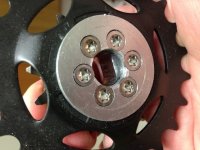
@crossbreak: i hope you enjoy that :) as an addition: i had to file away a bit of the screw heads as if didn't fit on the axle. but now it slips on very easily with very little play.

[youtube]dlbF-LgaH8Y[/youtube]
 
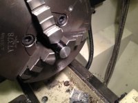
I made the 14mm double -D hole with a normal file by hands. Not that bad fit i'd say :p Tried milling but that didn't really work out

i had to file away a bit of the screw heads as if didn't fit on the axle

Ups.. i already turned them down on the lathe... this design is quite challenging, for the 14mm axles you dont get around special screws.. just not enough space in between the 30mm freewheel threads and the 14mm shaft.
 
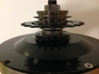
i had to install the IGH Sprocket the other way around. Otherwise there is just not enough clearance between pedal chain and wheel chain. In 9th gear the chains touched eventually.

Just try, due the simple+flexible design of this adapter it should be easy to adapt for you needs.
 
had a busy day at the workshop today. all parts are more or less done - most of them are. those needed to be fit in, depending on other parts, need to be finished as soon as possible.

all outer parts of the box where clamped together and brought to exactly 108mm width

14-03-13 at 14.07.34.jpg
motor covers - those need to be adjusted in size as soon as it can be done

14-03-13 at 15.57.47.jpg
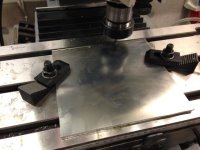
milling those plates

14-03-13 at 16.02.09.jpg
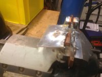
first try welding them. a total disaster. must be something with the gas. no gas - no weld.

14-03-13 at 16.43.11.jpg
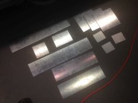
all parts that will be needed (excluding box side covers that will be made once the box is finished)

14-03-13 at 18.10.49.jpg
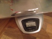
putting them on a scale showed that aluminium is NOT that super light as one would expect. on the other hand - it's 3mm thick. so quite oversized.

14-03-13 at 18.48.31.jpg
 
crossbreak said:
i suspect its density is around 2.7 :p if yours is more dense than your vendor has fooled you ;)
sure i could calculate the mm3 and multiply by 2.7 and i will have around 3kg. i did it the other way round.
it should be 3540cm2. i will double check and maybe return the plates if i got cheated *ggg*
 
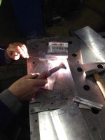
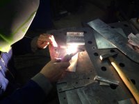
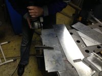
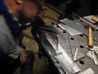
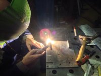
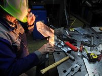
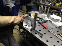
so yesterday was the long awaited day. all parts were cut and prepared and i showed up at the welder's workshop. i decided to let this handle a professional as the frame is critical ;)

i will just post some pictures to give you an impression of the process
2014-03-24 at 18.48.26.jpg

2014-03-24 at 18.48.35.jpg

2014-03-24 at 18.53.50.jpg

View attachment 7

View attachment 6

2014-03-24 at 19.08.40.jpg

2014-03-24 at 19.10.54.jpg

2014-03-24 at 19.19.02.jpg

2014-03-24 at 19.27.15.jpg

View attachment 1

2014-03-24 at 20.35.05.jpg
 
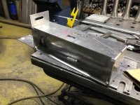
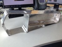
and this is what it looks like right now. there is still a lot of work to do. cleaning the surface, installing the motor side plates, making the side covers, motor cover, motor heat sink, drill holes for the bms ... but this is the first time i'm really confident that this project will come to a good end in the near future *ggg*

2014-03-25 at 13.10.04.jpg
 
Good going Izeman! Looks nice. Are you planning to have the aluminum assembly shown above welded to the frame next before you tackle the motor install? It will be a good feeling to get the frame all together and know the battery and motor compartment is all fitting in place and structurally sound. Looking forward to seeing the bike up and running. Awesome!

It looks like those blocker blocks that have been fillet welded in place could be tapped on there ends so you could run a machine screw into them for fastening your side covers to. Is this the plan?
 
hi wayne
next step would be to make the side plates where the motor is installed on. then weld those to the box, hold the box to the frame and see if the gears are in line (which is my biggest fear - we measured and calculated several times, but it's not really easy). if everything fits i can make the motor cover and the heat sink that installs to it.
then the box will be spot welded to the frame and i will make the little supporting triangles. so it can be welded all together. i'm still unsure if i will risk to weld to the steering bearings as the alloy will not be totally round afterwards :(
and yes. those little 10x10 blocks will be tapped with m6 holes to screw down the side plates and give some more structural support.
 
speed mode throttle is jerky. i can imagine it will not be very comfortable with middrive geared motors.
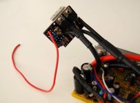
cyclone sells some middrives with kelly controllers. the controller for the stronger drives looks like a sine wave sabvoton.
http://www.cyclone-tw.com/order-3chain.htm

zombiess throttle tamer helps to make the infineons less jerky, but it will never be like a real torque mode controller.
i have tested the options with the CA as well but i did not like them..

izeman you can have a tamer from me if you want to try it out. i do not need it anymore.

http://endless-sphere.com/forums/viewtopic.php?f=31&t=51460

btw: very neat work
 
thanks for the offer. i definately will try that. please have it ready when we meet monday-7th. :)
does the throttle tamer work together with the CA limiting factors and throttle ramp features? i don't want to lose those. i still need power/speed limit on preset1 and full power on preset2. i just want to have a way to apply just a little power when you are in a very steep section and a lot of big stones and roots are in your way and you don't want the bike to do a burn out or wheelie.
 
you can connect the tamer between CA and controller or like normal between throttle and controller.
it should work together with all the CA throttle settings/features.

you have to look if the +5V regulator from the CA will provide enough current for it. it is written in the manual how much it will provide at given battery voltage.
the tamer drains about 20mA. the throttle a few mA. i think it should work with your battery.
with my 90V battery there was not enough current provided, so i powered the CA from the 12 DC converter.

i can not sure say if the tamer works with pot throttles, but i think it will do. i used a chinese hall thumb throttle. i was not able to do more tests etc. because i blew my controller.
 
I use my own throttle tamer which actually works like current throttle as soon as the freewheels engage. But eventually they engage quite hard. Its almost open loop control so out reacts much faster than the CA current throttle. Still it needs rpm feedback which does not work properly if freewheels are not yet engaged. This medicine just cures the symptoms. A real current throttle will always be best way of control for the driver
 
Back
Top