Leaf / leafmotor / leafbike high efficiency 1500w motor

Great looking motor. It does look like serious amounts of heat are getting generated when pushing it with the 26" wheel vs the 24" in that last mile per hour increase in speed going by the calculator. May be just the weight/ load is just a bit much for the bigger wheel. Controller looks a good match in your setup also. Look forward to reports when your trying other controlers / battery setups.
 
Finally got my motor installed and controller wired up. Still waiting on my torque arms to arrive, but was able to go for a test ride with the controller set to 30A phase current and even then it's impressive. Can't wait to get everything together so I can turn it up even further. Thanks for being the guinea pig on this one, Leaf no doubt will have you to thank for some sales.
 
speedmd said:
Great looking motor.
It does look like serious amounts of heat are getting generated when pushing it with the 26" wheel vs the 24" in that last mile per hour increase in speed going by the calculator. May be just the weight/ load is just a bit much for the bigger wheel.
Not really. As mentioned previously, the dyno plots show power at WOT resulting in two different top speeds -- the results are not directly comparable.
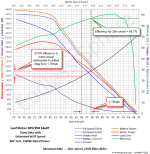
Here is a summary of the 24in vs 26in results:

26vs24inWheelPower.png
The concern is for the apparent increase in battery power from 1772W to 2077W going from 24in to 26in. This really does seem huge, but what we really want to do is compare the power at the same speed - which is not directly doable with the available plot data. If this was done in Justin's simulator, we would dial down the throttle on the faster 26in build to get the same speed as the 24in one (same motor power) and then compare the battery power.

Here's a explanation of most of the apparent huge 24vs26 power difference (24in estimated speed marker added to 26in dyno plot):

26vs24inWheelPower_plot.png
It's clear that we are getting slammed by aero drag because of the near-40mph speed. This is entirely a matter of the Load Line and has nothing to do with either wheel setup - it just takes a whopping bunch of power to add every mph at high speed.

As a comparison of the performance with our limited dyno data, it is perhaps more useful to look at efficiency. We know that to achieve the 24in wheel max speed we need 1569.5W. Any motor with any wheel diameter (assuming the same rolling resistance) will need to develop that exact amount of power to achieve that speed. The trick here is that efficiency gets us to the required battery power. So - we can just look at the efficiencies and get a pretty good notion of 'goodness' of the motor/wheel at delivering the required power to the road (1569.5W). Comparing the dyno data we see that the 24in vs 26in efficiencies are 88.56% vs 86.69% respectively at WOT. This is a difference of only a couple of percent so we really won't see a huge hit for using the 26in wheel.

  • The astute reader will have noticed that the 26in dyno data efficiency is at 37.82mph not the reduced speed of 36.03mph achievable with the 24in build. Here we rely on the fact that motor efficiency typically is not reduced much for reduced throttle settings - typically 0-1% at 80% WOT speed, only 0-5% at 60% max speed, and no more than 10% at 30% max speed. Efficiency drops markedly below 30% WOT speed. (This is not the same as the efficiency-vs-speed relationship shown in simulator or dyno plots which result from increased load not reduced throttle.) So - since we are only reducing the 26in speed to about 95%, we can reasonably use the '100% speed' efficiency because we know it's essentially the same.
Working out the math (to achieve the same speed):

  • BatteryPower = MotorPower/Efficiency

    24in: 1772.24W = 1569.5W / 88.56% (running WOT)
    26in: 1813.19W = 1569.5W / 86.69% (throttled down a bit)
So when throttled down to the WOT speed of the 24in build, the 26in build should use approximately (1813W - 1772W) ~= 41W more than the 24" build.

Anyhow, maybe just a bit more info milked from the dyno data... :)
 
Thanks Teklektik for the details. It was hard to tell numbers exactly based on the early separate charts. Understood the max speeds were not the same and can see much better from your latest overlaid chart post that speed difference makes up most of the load / losses. Would be interesting to compare the zero to 35 mph times of the two setups. As you mentioned before, there may be many other reasons to consider making this trade off of a little bit of top speed loss for various other small benefits. This motor running 88.56% efficient in a 24" setup is amazing compared to most all of the other hub motor charts I have looked at. Stellar also in a 26" wheel. Very interested in the controller setup as well. Not sure I understand what is going on exactly with the 120% speed setup. I am Sure we will see much more on this motor.
 
Well.... i need to be honest about this motor :|

It's now 80 degrees Fahrenheit here in Utah..
Doing 45mph for ~5 miles is now creating incredibly shocking amounts of heat..
I've seen 200C at the windings today :oops: :cry:

I can't believe it.. I do wonder if i've demagnetized the motor during long 45mph runs.. or if there is such a dramatic difference between ~65f and ~80f in regards to air cooling.

This is a great motor... but i think it is not up to the duty of my 45mph speed limit roads w/ mostly no bike lanes :(

This would be no problem if i could keep to 40mph..
 
Sorry to hear Nep. Sounds like it cooked, lightly toasted. :( Big difference in load at 40 vs 45MPH, 2100 vs 3000 watts going by the above chart. Hopefully you can get another one the same kv and lams to vent and see if it survives this load without burning up in your hot weather. Do you have any info as to what the controller is doing exactly at the 120% setting. Looks to be a good bridge between the smaller hubs and monster size/weight ones. Tempted to build with one just to check it out.
 
neptronix said:
Well.... i need to be honest about this motor :|

It's now 80 degrees Fahrenheit here in Utah..
Doing 45mph for ~5 miles is now creating incredibly shocking amounts of heat..
I've seen 200C at the windings today :oops: :cry:

IMHO, I don't think you ruined your motor. Well, if you have, then I've ruined one too, but I really doubt it. I don't run enough power to generate enough heat to do that. (I run wimpy power levels to maximize range.)

I see that behavior with my 9c hubmotors during voltage sag from the pack. I've brought it up in my thread but no one seems to really notice or think about it. Heat goes up, performance goes down. It happens in the bottom third of the pack capacity. This "effect" happened when I was running 18S/74v hot-off-charger and became pronounced from 68 volts on down.

The Crystalyte will do it too, but it's less prounounced and it happens at lower voltage sag. Performance goes down, heat goes up. Significantly enough that you can "see" it on the CA. At one point in my build thread I whine about needing to add a temp sensor so I can see what's going on with heat in the motor.

The graphs on both the simulator and the dyno stuff in this thread "point" to the phenomenon, but I there's this disconnect between the graphs and really what happens. I've been considering buying a datalogger just to get a handle on it, but I'd need good thermal data for it to be worth the trouble.

My next approach is going to be to add about 25% of the empty volume inside the motor in oil. (I don't want to fill it, just put in enough to "wash" over the stator and magnets to even out the heat distribution in the motor. Not just to see if I can "fix" the problem, but to give the motor a medium to reject heat into that I can then measure.
 
With 200c at the coils I would expect the drum /magnetic's to run quite a bit cooler. Still most likely near/over the 180F limit.

Magnet%20Characteristics.png

rare_earth_specification.jpg
 
Do you have a temp sensor embedded and monitored on the motor, Nep?

At the phase currents you are running, it would probably be wise.

I need to wire mine up to the CA3 I have sitting on my bench. - But I never push my motor hard for Long periods. Only 1/4-mile sprints. :wink:
 
speedmd said:
Big difference in load at 40 vs 45MPH, 2100 vs 3000 watts going by the above chart.
Spot on.

Nep's application is particularly trying - sustained 45mph speeds which put it way up there in the aero drag category. There's no getting around the size of the case and the heat dissipation at sustained levels - the ultimate issue. Interestingly, we note that the required 3000W to achieve 45mph is exactly twice the motor rating of 1500W. So - we might look at 2WD as a means to address heating by doubling the net case size....

Here's a summary of the data from the 26" wheel plot on the previous page (the 2WD speed determination is explained in the later 24" wheel post):

1WD-2WD_comparison_26inWheel48V.png
Comparing the 1WD and 2WD cases we see an increase in speed of 3mph, an increase in efficiency to 90%, and each motor carrying less than half the heat load of the slower 1WD case. At 1150W of the rated 1500W per motor, it will do 41mph all day long. It should sustain 45mph with a modest voltage increase or perhaps the funky controller 100+% speed setting to bump the motor power to 1500W/motor.

I really really don't want to precipitate yet another tiresome 1WD-vs-2WD OT discussion - this is just an observation about net drive efficiency and heat dissipation using stock unmodified motors.
 
Interesting comparing a dual motor setup. What I still am having trouble understanding is the 120% speed adjustment the controller is making to push this speed. Would think it is raising the phase voltage also to overcome the BEMF and spin it faster. No idea, just a guess.

With venting and some fins as John in CR did, it may run closer to this 3kw for some time. Looks promising.
 
speedmd said:
What I still am having trouble understanding is the 120% speed adjustment the controller is making to push this speed.
Zombiess had a very interesting post a couple years back:
Video proof - myths of 120% throttle setting and more!

The gist of it is that there seem to be two effects for Xie Chang controller speed settings over 100%:
  • the trapezoidal commutation waveform becomes increasingly square,
  • the commutation waveform is made about 10% wider.
Here's three quick snaps from Z's video showing phase waveforms:

zombiess_PWM_Study2.jpg
We don't seem to have authoritative explanation of the controller theory of operation or an engineering consensus as to the effects of these observed behaviors, but I might speculate that:

    • the faster rise of the waveform relative to the hall signal effectively advances the timing and
    • the wider and squarer waveform increases the effective (RMS) phase voltage (and hence phase current).
    If this is true, we might see an effective increase in Kv from the timing change at high speed and increased torque from increased available phase current. Together these should cause the motor to achieve a higher max speed.
 
I know this is disappointing to yall.. but I do not have a temp sensor, guys..
The motor is lightly vented on both sides.. i take these measurements by pointing a little turnigy temp sensor at the coils through a vent hole. I double checked to see if the temp sensor was off.. it is unfortunately not off.. :(

I have been periodically checking the motor at stops this way since i've vented it. Before, i would take the hottest point on the case and then figure the math on the internal temps based on justin at ebikes.ca's tests for the 9C here:

http://endless-sphere.com/forums/viewtopic.php?f=2&t=48753

When i see ~200C at the coil, the hub case is not so hot that i can't hold my hand on it. But i can feel heat coming out of it during a rest. I understand that this is too high of a temperature for the magnets, for sure.

I understand entirely that i am pushing this motor very hard. This is still a great motor, however my needs in this area are very, very demanding. It's not only continuous 45mph that i put this motor through, it's also that there is not a single piece of flat land where i live.. it's a constant 0-7% grade rollercoaster.

I would run this motor indefinitely if we had lower speed limits. You can't ask for a more efficient motor with such a low weight.. it hits peak efficiency at around 30mph cruising, which is PERFECT for an ebike in my opinion.

But I am going to upgrade to a MXUS 3kW to give me more headroom. This motor is surely damaged ( demagnetized ), and any future performance observations or numbers are going to be misleadingly poor.

I officially hand off the 'doing science' aspect of this motor to you guys.
 
ps, thanks tele for finding that post about 120%. :)
 
Thanks Tek for posting the link. Wondering what is the voltage at the top left of the grid around the 2 minute mark in the video is referencing. It clearly increases with the steps. Zombiess does also note a slight increase in voltage at the 120% setting late in the clip. One thing that caught my eye, was the bottoms of the PWM waves seem to go lower also and certainly the longer square wave duration. May be wrong as it is hard to tell unless overlaid to see the overall height top to bottom of the pwm forms as they progress. If it is taller, could this aid in absorbing/ working with BEMF better? Sort of like increasing suspension travel will improve ride /drive efficiency on bumpy roads. Thinking also as others have already suggested that it may be putting current into the coils before and after the BEMF is fighting it. The fact that it drops out of pwm and pumps out a solid square wave is most likely just plain better at fighting the bemf. Solid DC into a coil drives current way better than frequencies do. Something seriously cool with this setup and I want to know what it is exactly. :)
 
neptronix said:
This is still a great motor, however my needs in this area are very, very demanding.
...
I am going to upgrade to a MXUS 3kW to give me more headroom.
Ya - your situation really needs more rated power from the gitgo - it's just a little too challenging to go after a 3000W problem with a 1500W solution.

Anyhow, sorry about the crippled motor although perhaps Leaf might sell you just the central magnet part of the case so you could restore the motor for another use. They do sell the complete side-cover/stator/axle assembly, so maybe they will sell the remaining part separately as well.

Thanks for all your effort and reporting on this motor - quite a nice product. :D
 
Is the magnet strength easily measurable? Even by a crude comparison method? Would be interesting to see what / if they actually degraded significantly by the heating. Imagine it is a significant job to knock out the old magnets and swap in some fresh/ upgraded ones. Hopefully the whole magnet barrel can be found /scavenged for not much money and research/ abuse go on. :)
 
Contacted Leaf with some questions and they got back with some added details:

  • They have 80 and 100mm double walled rims available. No 65mm.
  • They can install a temp sensor - special handling takes an extra 1-2 days. They use a two wire hookup that doesn't share a Gnd with the halls (the best arrangement), so thumbs up. They didn't specify a type but I did not pursue this detail owing to the fact that comms are a little slow, the CA can handle a wide variety of temp sensors, and replacing the sensor with an exact preferred type is trivial if the wires are already run.
Actually, email stuff went smoothly and they seemed quite helpful and courteous.
 
Just ordered mine, with the following options, (all of which were free of charge):

5T winding
4mm phase wires. This is twice the "stock" diameter and involves a different shaft and side cover. You lose the brake rotor mount, which honestly I wasn't really going to use anyway. Hopefully this means a solid shaft if they have to change the cover. We'll see soon...
Internal temp sensor added.

I'll post an update when it arrives so you can see what the upgraded phase solution looks like for real. Damn, now I realize I should have asked if they could make one with a freehub cover... Anyone know of any bolt-on freehub options out there were I to make my own right-side cover?
 
Hello

Kodin, I have a question, do you know how many strands your 5 turn motor is going to have ?

IIRC the 4 turn has 16 parallel strands per turn. The 5 turn should hold at least 12 but I'm hoping we get 13, every strand of copper fill helps.

Take care and have fun - DS
 
mrDS

I got some info from Leaf Bike about this motor. Standard winding is 16*4 Turn( about 630 rpm) ,They said the 13*5 Turn winding is about 520 rpm . So looks to me like 13 strands it is.
I just ordered one with the temp sensor, 13*5 Turn winding.
 
Thank You Neptronix for the info regarding this motor, I have learned a lot from your post and videos. Your test of the motor gives me the confidence that this motor will work well for my less demanding needs. :D
 
Back
Top