Liberty Trike controller upgrade

icrude

100 mW
Joined
Aug 19, 2023
Messages
36
Location
Mission Viejo
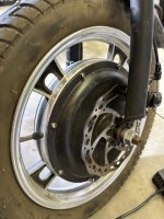
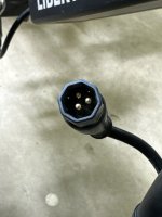
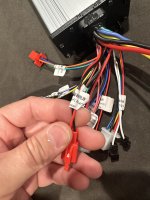
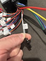
Hey everyone, so I have the libertytrike, and we are trying to change the controller to go from 36v to 48v because this thing is limited to 12mph. I’ve attached some photos of the original setup and motor connector. I got a new controller (link attached) and have the three main wires hooked up for the motor (green yellow blue) but the motor doesn’t want to work. We aren’t completely sure how to wire the throttle up. It has red, black, green, blue, and yellow but the new controller only has black white and red for throttle. The original blue and yellow we think is for the reverse which we don’t need those. So we tried red to red, black to black, and green to white. The motor does seem to be getting power because it locks up when we twist the throttle. So I’m not sure if there is something obvious we’re missing. We didn’t wire up the hall wires (does that matter). Any ideas would be appreciated.


Attachments

  • 71407002380__A4C409DC-1D7A-4F01-B0D9-4EF420A60F19.jpeg
    71407002380__A4C409DC-1D7A-4F01-B0D9-4EF420A60F19.jpeg
    116.3 KB · Views: 4
  • 71407003470__7503990C-A165-41B6-89BC-5439202DE351.jpeg
    71407003470__7503990C-A165-41B6-89BC-5439202DE351.jpeg
    75.8 KB · Views: 6
Got it figured out! I did need to wire the other motor wires together. Works like a charm now.
Be careful riding that thing faster than 12 mph. Heck, be careful riding it at 12 mph. It's only 24 inches wide with high seating, so it's a tipover waiting to happen. And unlike some other mobility scooters, it isn't ballasted low in the base with lead bricks. A good followup retrofit would be to add a wider rear axle to stabilize it at speed.
 
So I have a trike that has the 6 hall sensor wires (plus the 3 main motor wires). I already purchased this controller (which I can return but wanted to double check first) and on the Amazon page it said “no for hall motor” in poorly written English. I’m assuming that means it won’t work for motors that have the 6 hall wires? It does have the right 3 bigger motor wires, and another white connector that looks like it’s for the 6 hall wires (and it’s even labeled for the motor) but it only has 5 wires. Could this be used for the hall wires and maybe just missing one?

 
Last edited:
Just hook it up and try. It's Prime so you can return it if it doesn't work.

1/2 the reviewers said it works, 1/2 said it didn't work correctly. Here is one important review: "After replacing hall sensors, bi-passing the little board in the motor and, connecting directly to the hall sensors, replacing the wiring harness with network cable and three controllers later this one works!"

Personally I'd return it. Keep looking. I have a similar one coming in the mail: Amazon.com

There are a few identical to this one from different manufacturers. The nice thing is that in one of the diagrams they clearly show all the pins for each wire group, so you can match it with the motor, battery, throttle, and PAS (if you are doing PAS). What do you know, it came today. To the wrong address, have no idea which neighbor accepted it.
 
It looks like the white hall wire is the only wire missing in this controller. Is that important?
Do you know if your motor is direct drive or geared? If not, a pic would help. There are 5 wires typically used for the hall sensors; red and black for the 5V supply, and yellow, blue, green for each hall sensor. The connector typically supports 6 wires, with the 6th, usually a white wire, supporting either a speed or temperature sensor. If it's a geared motor, it's usually a speed sensor. A speed sensor is needed with a geared motor because the usual method of using one of the hall sensor wires to determine speed does work when the motor isn't powered (when coasting) for geared motors, so a separate speed sensor is installed in the motor. Not all controllers support a separate speed sensor input, so if not, you may only be able to see your speed when you are on the throttle and not coasting. It will run without it, if that's not important to you.
 
In the description it says dual-mode, so it can run with sensors or without.
Dual mode controllers IMO are the best choice since you can still run the motor if the sensors break.
Also the 6th wire is temperature, not hall.
 
ahhhh I just noticed that this controller doesn't have a connector for the screen!
Even if it had a display connector, the likelihood it would work with your display is approximately zero.
 
Just connect motor, battery, throttle and then connect the black and red wire together for ignition and the 2 white wires for 3 seconds or so for initial setup and off you go.
 
Why wouldn’t it work with my display? How is anyone supposed to turn this on if it doesn’t have a display connector?
A lot don’t have displays (some folks prefer no display). Many controllers, with and without displays, have a connector (sometimes labeled “key switch”), that you connect to a handlebar mounted switch for on/off.
 
Oh but what about menu settings like voltage?
You get what you get. Most controllers that support multiple voltages usually either autosense the voltage of the pack and set things like LVC automatically, or they don't sense, work with a broad range, and only supply LVC for the lowest voltage. I have a controller that supports 60V and 72V and it has a jumper for choosing between them.
 
Why wouldn’t it work with my display?
They're isn't an industry standard for controller data interface or even connector style or pinout. I'm my observation, every different controller that supports a display is committed to one brand of display (Kunteng, Bafang, etc.) and doesn't work with any other kind.
 
Why wouldn’t it work with my display? How is anyone supposed to turn this on if it doesn’t have a display connector?
They're isn't an industry standard for controller data interface or even connector style or pinout. I'm my observation, every different controller that supports a display is committed to one brand of display (Kunteng, Bafang, etc.) and doesn't work with any other kind.
I have work in progress list of displays and the controller manufacturers compatible with them. Note that the list is for stock displays. Some displays have open source firmware available to make them work with other manufacturers with custom features, but stock displays only work with controllers of the same make.
 
Just connect motor, battery, throttle and then connect the black and red wire together for ignition and the 2 white wires for 3 seconds or so for initial setup and off you go.
so the only white wires are a learning connector, is that what you’re talking about? And the black and red wire are this anti theft connector?
 

Attachments

  • IMG_0993.jpeg
    IMG_0993.jpeg
    1.5 MB · Views: 6
  • IMG_0992.jpeg
    IMG_0992.jpeg
    1.7 MB · Views: 6
I’ve got anti theft alarm power, anti theft alarm signal, multiple data meter, low level brake, electric door lock (must be connected), reverse gear, high level brake, conventional meter, shift tree speed gear, special for different motor, jog three speed gear, learning wire, speed control handle, red and white for power, yellow blue and green for motor, and the hall looking connector but with 5 wires not 6 (no white)
 
Sounds good to me! Connect electric door lock and then the self learn, the motor should spin slowly. If it's turning the wrong way unplug the learning wires and reconnect them. Once it's spinning in the right direction unplug them an you're ready to go.
 
Sounds good to me! Connect electric door lock and then the self learn, the motor should spin slowly. If it's turning the wrong way unplug the learning wires and reconnect them. Once it's spinning in the right direction unplug them a you're ready to go.
Don’t hate me but the electric door lock is just a red wire nothing else. What do I connect it to? Do I not need to connect the 5 hall wires?
 
Back
Top