powersupply
100 W
I am enhancing my controller and noticed a weird thing:
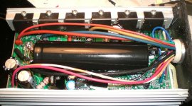
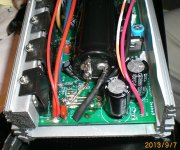
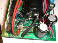
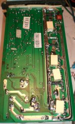
There are 2 x 470/50V caps connected directly to the + and - of the incoming battery wires.
From there, in the - path, there is the shunt and behind that is another (same type) 470/50V capacitor, located at the FET power "bus".
Exactly the same arrangement like in the second picture (PA270018.JPG) in
http://www.endless-sphere.com/forums/viewtopic.php?f=2&t=3896
Now I understand that the incoming DC needs to be buffered, but the FET's need very much power for their rise times, so shouldn't the 2 x 470/50V caps berather positioned behind the shunt???
And just one 470/50V for buffering things like the two voltage regulators etc?
I see that the FET power "bus" is quite crowded, might that be the reason???
Here is my actual question:
I have a REAL low ESR 1500uF/75V cap which I would like to implement, where should I put it, directly at the incoming +/- from the battery or at the FET bus?


