Make: Fechters' Braking Regen Add-on for BLDC Motors

I'll have to think about it more.

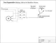
Instead of the brushed controller/resistor thing, you could just use a very large transistor on a very large heat sink and dissipate the power that way, using the transistor as a variable resistor. Varying the current (braking force) would be fairly simple.

I'm not sure what kind of transistor you'd need to dissipate that kind of power.
I've seen some gigantic IGBT modules on eBay that would probably do it.

I think pumping the power back into the batteries will not shorten their lifespan significantly as long as the charging current is limited to a safe value. Most batteries will have a longer life span if they are not discharged fully.
 
I'm keen to hear your solution. Another reason why I wan't to avoid pumping it back in to the batteries is that I wan't to keep it super simple.

If I'm only going stop start stop (up to about 30km/h) is it really worth trying to return it to the batteries anyway?

I guess if I can use the heat sink method and get that to work then at a later stage I just have to set up some sort of voltage regulator and feed it back to the batteries.

I can tell by the other threads that you love a challenge.... so I'm interested to see what you come up with :)
 
I failing to understand how you can regen unless you are going very fast, ie over speeds that you normally travel or speed that your batteries can't take you too, downhill only. At that point you then have high voltage coming out of the windings and can push them back into the batteries. But at normal stop and go speeds isn't the voltage too low?

Fechter: Those IGBT transistors are awesome. Couldn't we use those in a modified crystalyte controller? Instead of 12 fets we have 3.
 
Normally, the motor voltage won't be higher than the battery voltage unless you're going faster than the no-load speed of the motor. If you go really fast downhill, you will start getting regen with a typical controller, which will limit your top speed downhill.

In a typical implementation of regen, the motor and controller are working in a switching boost converter configuration.

In the boost converter configuration, we can boost the voltage to way higher than the battery voltage, so it is possible to charge the battery even when the motor is going quite slow.

We do this by momentarily shorting the motor windings with a FET switch. When the switch closes, the current in the windings starts to build. When the switch opens, there could be several hundreds or even thousands of volts of potential across the windings, which is directed back to the batteries through diodes. Without the diodes, the voltage spike would fry the FETs. The switch is operated at a high frequency, so that the peak current is close to the average current, and the duty cycle of the switching will determine the current the same way it does in a normal controller driving a motor. If the duty cycle reaches 100%, the motor will be completely shorted, and there will not be any more regen to the batteries and the motor will be practically locked up.

By adding a current monitoring circuit, the regen can be limited so the current to the batteries never exceeds a given level. With lead-acid batteries like Hawkers, you can pump 100 amps into the batteries. With other batteries, the maximum charge current may be less. You also need to limit the current so you don't lock up the wheel or rip the axle out of the dropouts.

IGBT's are pretty amazing. They would be good if you wanted to make a car-sized brushless controller. One disadvantage of IGBT's is they always have about a 1v-2v drop across them when they are on. This means they will dissipate a considerable amount of heat and will need a massive heat sink. At voltages of 100v or less, FETs will have far less voltage drop and heat dissipation (loss). Above around 200v and 100 amps, IGBT's will start to have less loss. IGBT modules you find on eBay are usually rated for 600v and up, with currents in the hundreds of amps.
 
OK, here's one possible way to do completely non-regenerative braking. The transistor will need to dissipate at least half of the total maximum power, the other portion would be dissipated by the resistor. You could skip the big resistor if the transistor is big enough to dissipate all the power.

The transistor is going to get really really hot during braking and will need a very effective heat sink.

The on/off swith and control pot can be remotely located and don't need to carry too much current depending on what transistor is used. I think an IGBT could be used in pretty much the same circuit.
 

Attachments

  • Brushless Regen 3.jpg
    Brushless Regen 3.jpg
    20.2 KB · Views: 4,603
Fechter,

When you say "really really big transistor", do you mean big as in physically? How "big" and heavy are we talking? I'm not all that familiar with the Darlington transistor.

Having said that,

Are you confident that returning the charge to the LiFePo4 batteries wouldn't hurt them?

Perhaps I'm better off forking out for one of the Kelly BLDC units that I've seen in another thread?
 
I'm pretty sure that returning charge to the batteries won't hurt them as long as you don't ever exceed a certain current. I don't know what that current is, and it probably depends much on the particular battery. A123's can take a lot I bet.

Does anybody know this? How much current can a LiFePO4 take on charge, as long as you never exceed the maximum allowable voltage? The same as discharge? Half?

By really big I mean one that can dissipate like 500 watts. It would need to be physically big to do that. I'm not sure if such a thing exists or how expensive it would be.

I thought of another approach that would avoid this. You could use a wire resistor like Gary's, but have multiple taps acitvated by FETs. When the FETs are on, they won't give off much heat. All the heat would be in the resistor. The FETs could be switched on in sequence, even automatically to keep the current near the desired level. This might be easier than a giant switch.
 
With a123-based packs, each 2.3Ah cell can safely take up to about 20A, which is about 8C. If you have, say, 4 cells in parallel, in a 9.2Ah configuration, that would mean it can be safely charged at up to 80A, which is probably a lot more than any regen setup will need to do. LiFeBatt cells can be safely charged at 3C, or 30A, for 10Ah setup. With the various Chinese LiFePO4 variants, which have much lower "C" ratings, I think the charge limit is 1C, but most of these are much bigger cells, like 20Ah or 25Ah, so they will still take 20-25A. These are all continuous charge rates, so I think all will take quick bursts of higher currents just fine.

I've been doing some tests with the resistive setup on my wife's Townie and the max "burst" current I've seen on the Watt's Up I have connected between the rectifier and the coils is 53A. That is with the bike going about 30 mph and then dumping everything through a 15-foot coil of 18-gauge wire. Amazingly, it doesn't even get that hot. I can keep my hand on the coil without a problem. Neither the motor or the recitifier gets hot either. The coil is wrapped around the frame:

ebikes-25.jpg


The second coil is about 11-12 feet of the same wire. I have two handlebar-mounted pushbuttons, on that routes through both coils, and then the other that only connects the larger one, for the maximum braking power. At 30 mph, with a 5304 on a 26" wheel, hitting the "max" button creates a very strong braking force, much stronger than any bike brake I've tried, with the possible exception of motorcycle-like hydraulic disc brake, with an 8" disc. Even then, I'd give a slight edge to this "e-brake" setup. With the two-coil setup engaged, the max current generated is about 40-42A, and it still has braking power at least equal to any stock brake setup, and may actually still be stronger. I'm using this as a complete replacement for the front brake because stock, this bike came with a hub-type brake up front, and the fork does not have regular V-brake mounts. If you are adding a plug/regen brake setup to supplement an existing brake setup, I would think you wouldn't need any more than 30A-35A, if that much. I'm a big guy (6'3" 260 lbs...) on a heavy bike, so it doesn't get much worse case than that. :shock: :D

Whatever setup you do, one thing to keep in mine is that you need torque arms that will lock the axle in for both directions. This is especially true for front-mounted hubmotors. I ended up having to use two torque arms, one on each side, in opposite orientations to each other.

-- Gary
 
OK, a couple more ideas:

If you're running cheap Chinese Lithium batteries and really don't want any regen, you could do the setup indicated earlier, but add a large (<1,000uf) capacitor across the output of the bridge to keep any regen from getting back to the batteries.
Brushless regen 4.jpg

The cheap controller is just a FET switch with adjustable duty cycle. All the energy will be dissipated into the resistor, which would be a wire thing like Gary's. By adjusting the duty cycle (throttle input) to the braking controller, the braking force can be varied continuously, up to a maximum determined by the resistor.
 
Regen has without any doubt cooked my nimhs lifespan almost exactly by half, & this is despite supposedly sofistimacated pic micro based architecture in both the bms & motor controller monitoring battery temp with direct control over regen.
Other chemistries probably fare better as they don't heat up as much (endothermic?) as nimh during charge, or discharge for that matter, which makes nickel types particularly vulnerable to damage from regen currents.
 
The regen in my Honda Civic hybrid seems to work fine, but it does have a sophisticated BMS.
What kind of regen fried your batteries?

Unless you live at the top of a hill, normally the battery will be drained enough to accept all the charge you might get from regen. If you ride up a hill, coming down the same hill, you might get 30% of the charge back if you're lucky, so overcharging the batteries seems unlikely in most cases.

When I saw the picutre of Gary's setup I got to thinking that if you wrap a bunch of wire around a steel tube (like a bike frame), it will probably make a pretty good inductor. This might be good. Since the 'resistor' has inductance, it's effective resistance (impedance) will increase at higher frequencies, and decrease at lower frequencies.

At higher speeds, the phase currents are at a higher frequency, so if you got enough inductance, the change in impedance could exactly balance out the change in voltage and keep the current constant over a wide range of speed. Cool. Passive current limiting.

A bridge rectifier will add the 3 phases and knock out a lot of the AC, so you would want to avoid this. They're big and expensive too.

So you could implement braking by having 3 coils and 2 switches. The coils could be either delta or wye connected. I drew the wye configuration. If you only activate one switch, you would get partial braking, both switches, maximum braking.

Brushless Resistor Brake.jpg
 
Now on the other hand, if you're like me and you want to recover as much energy as possible into the batteries (great for lead-acid), then I came up with a better approach for that too.

A bridge rectifier, as pointed out above, is big, expensive, and will get hotter than crap on a long downhill, needing a big, expensive heat sink. They also are slow to switch, so would be quite lossy in a switching setup at high frequency.

To avoid this and the losses that go with it, you could simply use three FET switches that short the phase wires in switching mode. When the FETs are switching, they should not dissipate much heat, and not need a very large heat sink (assuming good FETs). Inside the main controller, even at zero throttle, at least one low side FET is usually on at any given time. This will keep the ground reference the same for the brake unit and the main controller.

All three FET gates can be driven in parallel and turn on at the same time. They don't have to care where the halls are for braking, so that makes wiring easier.

The PWM unit still needs to be worked out. I think there are some cheap PWM chips made for switching power supplies that would work. It should never reach 100% on, but up to 95% might be OK. It would ideally have some kind of current limiter, and many of these PWM chips are already designed to do this function.

Here's the basic topology:
Brushless Regen 5.jpg
 
The Kelly controller is going to pump all the regen back into the batteries.

I don't think we know for sure whether this is a good thing for lithium batteries.
I think it won't hurt them, but there's another test for somebody. Is there data for cycle life vs. depth of discharge for these new lithiums?

My guess is the Kelly will work great. Still yet to see an actual test on one....

My adapter might make sense if you already have a good controller and just want to add regen. It might be cheaper, especially if you do it yourself.
 
I've been watching this thread for a while & it looks like a soloution to my rwd 5304 in which i want to eliminate the rear disk brake & use a non regenerative
brake setup ...

Could anyone do a parts list of what exact part should be used?

And please any pictures if possible.

thanks
-steveo
 
The setup that GGoodrum has posted above looks pretty close. If you wanted to try the setup with no bridge rectifier, then my 3 coil, two switch setup above might be worth a try. Each coil would be about a 15-foot coil of 18-gauge wire. You might need to play with the exact length to get the right amount of braking. The coil needs to be a single layer and would probably work best on a piece of steel tubing, but if all you have is aluminum, that would work too. I'm not sure what switches Gary used, but they would need to handle quite a bit of current.

On one of my scooters, I rigged up a lever-type microswitch to the brake mechanism that seemed to handle the current OK. It was rated for 20 amps.

If you're not using the rear brake at all (you could use a rim brake?), then you could possibly use the rear brake cable to activate the switches in sequence. The switches could be placed in a box and acivated similar to the "waterproof throttle". http://endless-sphere.com/forums/viewtopic.php?f=6&t=2522&hilit=+waterproof+throttle
 
Hey fechter..

Yes i would like to do my build like goodrun's .. isn't he using a rectifier ? ...i'm not even sure i know what that is .. isn't it underneath his key .. those to square things ...

Could you do a simple drawing to explain in laymans...much appriciated .. I saw you last drawing above but i don't know how you hook it up..

-steveo
 
I'd recommend trying the no rectifier approach.
This is because nobody has tried it yet and I'm looking for a guinea pig :twisted:

Well, it's easier to hook up and lots cheaper too.

I'll try to make a pictorial diagram for you. Might be a little while before I can draw that.

Meanwhile, either way you need some switches. I'm open to suggestions on those. Perhaps something from an auto parts store. I can find sources on the web if you want to order.
 
I'm up for trying the cheap way .. no doubt :) ...;

as long as i won't blow anything or break anything .. i may have some decent switches laying around .. how many amp do they need to handle?

i think i have once from a Pentium 1 power supply .. should be decent for the test ..
 
Hi Steveo --

I'm using a 100V/35A 3-phase bridge rectifier. The part number is 36MT10-ND and I got it from Digikey. Here's the datasheet: http://www.vishay.com/docs/93565/36mt.pdf.

Originally, I used two single phase rectifiers, which is what is shown in the pics I posted. I've since replaced these with the single 3-phase unit, which is basically the same size. It is mounted to a piece of aluminum, which acts as a heatsink, and the aluminum piece is attached to the frame.

I'm actually using two pushbuttons from Radio Shack, along with two coils of 18-gauge wire, which are wrapped around the frame. One is 15 feet, and the other is about 11 feet. One button connects both coils, and the other button only connects the 15-foot coil.

The stopping power of the two-coil setup is very strong, and hits about 50A peaks at about 30-35 mph. The single coil setup is almost too strong. It really puts a strain on the torque arms. Yesterday I got up to about 32 mph and hit the button. It was up to about 52V. When I hit the button, it almost threw me off, and the WattsUp recorded a peak of 73A.

Because the braking power is variable with speed, I really don't think a two-button/two-coil setup is required. I would just use one coil of around 25 feet.

-- Gary
 
Hey goodrun ..


i'll have to see if they can ship me the 100V/35A 3-phase bridge rectifier (36MT10-ND) to woodbridge ontario .. i wonder if i could find them on ebay ? ...

I'm ok with a single coil system for now; if required i'll got for a 2 coil system..


could post a pic showing exactly how to build this non-regen brake with the rectifier installed or how yours is installed..

much appriciated ...

thanks
-steveo
 
steveo said:
Hey goodrun ..


i'll have to see if they can ship me the 100V/35A 3-phase bridge rectifier (36MT10-ND) to woodbridge ontario .. i wonder if i could find them on ebay ? ...

I'm ok with a single coil system for now; if required i'll got for a 2 coil system..


could post a pic showing exactly how to build this non-regen brake with the rectifier installed or how yours is installed..

much appriciated ...

thanks
-steveo

It actually is quite simple. Here's a drawing:

Resistive%20eBrake.gif


This isn't to scale, obviously, but you get the idea. :)

I'll try and get some better pics, later today.

-- Gary
 
Thanks for doing the drawing Gary .. I will try to get that part to so i can get my resistive braking going..


Fechter ...

When you can get that drawing without rectifier up so we can all see the difference ....Thankx!!!
 
OK, here is the simplest possible configuration:
Brushless Resistor brake.jpg

By only tapping two motor wires and no bridge, the braking current will be only passing through 2 of the 3 motor windings.

If you were doing really long downhills, it could possibly cause the motor windings to overheat, but with an X5 motor, overheating would be pretty hard.

The two coil configuration can evenly spread the load in the motor windings, but requires an additional switch contact. This may be unnecessary.

The length of wire in the resistor coil depends on what kind of motor you're running and your top speed. A 5303 will need fewer turns, a 5304 or 05 will need more turns.
 
Back
Top