Make: Fechters' Braking Regen Add-on for BLDC Motors

lazarus2405 said:
Also, on a completely unrelated note, can I connect the reverse/forward key in series with the power button on the analog clyte controllers, for an extra measure of tamper resistance? I've been running with the silly reverse disconnected, and I figured that might be a better use of a key switch.


Yes, that's a good idea and will work fine. Just double check that the switch is open in forward, otherwise you may need to join the reverse wires.
 
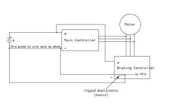
One way to make the current limiter work on regen would be to remove the shunt inside the braking controller and run a pair of wires out to the main battery connection. The section of wire between the battery negative and the main controller can act as a shunt if the resistance of the wire is high enough. The length / gauge of this wire can be changed to adjust the limit. A longer / skinnier wire will give a lower current limit. As I recall, about a foot of 10ga. is around 1 milliohm, which is near a typical shunt value. You'd probably want a bit more resistance than that to get a lower limit.

There might be a way to tweak the amplifier circuit that's looking at the shunt voltage to make it more sensitive, but I have never reverse engineered that part of a YK-xx controller.

Here's the overall layout:
Regen Controller current limiter1.jpg
 
Right, I get it. That's a good idea. Easy, too, it seems.

I haven't decided how exactly to inhibit the throttle yet. Instead of a pot box, I'll be using just the half-twist throttle mounted on the opposite handlebar so that it turns in the opposite direction. That'll be the most intuitive solution for me. The question then becomes how to close the ebrake circuit before the throttle sends a signal. Since the throttle has some movement before it sends a signal above 1v, I should be able to add a reed in there. I just think it'll be a tad difficult to arrange things. Should be fun...

Also, on an unrelated note, I had a lot of success with your low-end throttle response mod. Something so simple like that should really be standard.
 
When I mount my FETs to the inside of the case/heatsink, how do they need to be insulated? Will thermal grease electrically insulate them, with insulating grommets on the screws?
 
You should be able to recycle whatever insulators were there to start with. Grease alone is not insulating. There needs to be a silicone pad or mylar sheet between the tab and the heatsink. The screws need insulators too. You can test resistance after you install them to make sure they are insulated.
 
lazarus2405 said:
If I had to ballpark it, I'd say 25a-75a, depending on a lot of things. Ggoodrum said that his was pulling 30-50 amps from his 5304/26" setup stopping from ~35mph using 26' of 18awg and tapping all three phases through a bridge rectifier. No clue about the volts. I could connect a cheap analog ammeter and see what I get. My brake is installed at the moment, using 17' of 22awg, and it sure stops the wheel, but I have no idea how strong it is.

Hubmotor: Golden Motor 500W 36V

I have done this setup with a proper coil (varnish not vinyl), two wires from the motor, and it gave a bit of braking power. Yes it is giving that good old rumbling. Yes it gives proportional-to-the-speed braking power. I shortened the coil by a good 4 feet. Still not much difference. I decided to just give it a try with no coil whatsoever, and it didn't just skid the wheel. In fact it just slowed down the same way as with the coil!

My pushbutton switch is a 10A 120V. Wire is 18awg.

What am I missing here?
 
Your motor has enough winding resistance to totally absorb the braking. A motor with a higher no-load speed will also produce less EMF, so less resistance is required. I've heard of others who simply short out the motor. If you were using a 5305, it would lock up or twist out the axle for sure.

If you want more braking, you can use a double throw switch and short all the wires.
 
It will cause the motor to heat up more. As long as it doesn't get too hot, it should be OK.
Keep an eye on motor temp.
 
I tried it on the three wheeler, it did not work so well. I think because bike is so heavy. I tried less and less coil till i was afraid of damaging the motor. It slowed it down but made an god awful noise doing it lol. I just added a set of bulldog brakes to the back side of forks and use both sets on the front wheel with a dual brake lever and now i can lock up the front wheel if needed. 425 lbs takes a lot to stop..lol.
 
fechter said:
It will cause the motor to heat up more. As long as it doesn't get too hot, it should be OK.
Keep an eye on motor temp.

Well, so far I haven't made long runs as it's pouring outside and looks like it will be for the next week, but shorting out the motor (works without even using the batteries!) slows it down well, with 2 phases creating that rumbling (I'm used to it on electric skateboards which are a lot noisier and -powerful- when they regen-brake) and all 3 phases being smoooooth. Not extremely powerful, but good enough braking. So I don't see it as being a big problem for me since I won't have any downhills to do; looks like the engine will not warm up much on braking.

Thanks for the help!
 
fechter said:
A motor with a higher no-load speed will also produce less EMF, so less resistance is required. I've heard of others who simply short out the motor. If you were using a 5305, it would lock up or twist out the axle for sure.quote]

:shock:

I just hope my regen braking idea would not do that.. even if i brake from 60kph to 0kph too faster... :shock:


Doc
 
.
.
Cool thread, found it via Google. Never seen this forum before.
On the subject of an emergency brake, with the characteristics of:

- Highly reliable
- Super simple
- Cheap

I like this design, which is identical to others that have been posted:

MethodsEbrake.jpg


I wanted to have a panic button that I could hit if my mechanical brakes failed. Will have to analyze heat effects to drive efficiency before I agreed that this is what I would want to use as the primary braking system. My usual goal is to keep the motor as cool as possible, especially when running in the thousands of watts.

As far as Regen, there are a hundred ways to skin that cat. Some clever ideas have been posted. Nice work.

I also like the idea of using the 36MT Three Phase Bridge with a single resistor or. . . Just add a couple of smoothing caps, a diode, and your battery and you have your basic regen. Simple AC-DC converter.

-methods
 
methods said:
I also like the idea of using the 36MT Three Phase Bridge with a single resistor

After much reading it's sounds like this is the way I want to implement my plug brake for smoothness and maximum braking. Quick questions... the three phase bridge with a single coil loop and switch... will the switch still need to handle max allowable current for the brake or is the rectifier taking the load?? I'm too stupid to figure that out sorry, but based on the diagrams etc. I'm assuming I'll still need a heavy duty switch... I'm having trouble locating one. Any recommendations? What switches are you folks using?

This'll be on an 84v rear 504 in a 24" going down 1,600ft hill. Want to generate enough motor braking to reign in over speeding (keep it to around 25mph), but not over heat the motor during the 5mi decent. Rear v-brake has been removed. Front will stop me mostly. Etc. Thanks for switch links!
 
Yes, the switch has to take the full current. The rectifier will get hot too, so it needs a heat sink.
 
pwbset said:
After much reading it's sounds like this is the way I want to implement my plug brake for smoothness and maximum braking.

I tried the simple method using a coil of wire between 2 of the phase wires (connected to a 30a house switch) on my front wheel golden motor (no front brakes at this stage so I really need something!) and it was shuddering quite a bit. It felt like using rim brakes on a buckled wheel and sounded like it was hurting the motor so I was reluctant to use it.

Fechter, would adding a coil to the 3rd phase or using a rectifier eliminate this ?
 
fechter said:
Yes, the switch has to take the full current. The rectifier will get hot too, so it needs a heat sink.

Any ideas on a good push button switch to use? I search and search and can't seem to find anything over 6a. :|
 
Guys, just be carefull with that braking solution! :shock: your dropout MUST be very STRONG!!!

The bad experience that happened to Methods 2 weeks ago proove that.. and only with regen!! not braking!!

An axel that you change the rotation of the torque constantly will loosen and one day spin...and the famous POWERFULL X5 dropout saga will comeback again and again! :!:

Personally the only way i would accept to use the regen braking on an X5 would be if i previously welded the axel directly on the dropout!!

Doc
 
pwbset said:
fechter said:
Yes, the switch has to take the full current. The rectifier will get hot too, so it needs a heat sink.

Any ideas on a good push button switch to use? I search and search and can't seem to find anything over 6a. :|
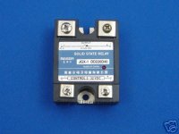
What about a SSR on the DC side of the rectifier bridge? You might even be able to use the braking controller signal to activate the SSR
0d4e_1.jpg

http://cgi.ebay.com/Solid-State-Relay-SSR-24-220V-DC-40A-Heat-Sink_W0QQitemZ220323307975QQihZ012QQcategoryZ36328QQssPageNameZWDVWQQrdZ1QQcmdZViewItem

I used a couple of AC SSR's on my home build 10' wind turbine controller, for dynamic braking.

Story here: http://www.fieldlines.com/story/2008/2/29/17834/0773

Blessings, Snow Crow
 
Hyena said:
pwbset said:
After much reading it's sounds like this is the way I want to implement my plug brake for smoothness and maximum braking.

I tried the simple method using a coil of wire between 2 of the phase wires (connected to a 30a house switch) on my front wheel golden motor (no front brakes at this stage so I really need something!) and it was shuddering quite a bit. It felt like using rim brakes on a buckled wheel and sounded like it was hurting the motor so I was reluctant to use it.

Fechter, would adding a coil to the 3rd phase or using a rectifier eliminate this ?

It may not completely eliminate it, but it will greatly reduce it.
It don't think it would hurt the motor electrically, but could mechanically (shake the axle nut loose or something).

The solid state relay idea is good. I would suggest using two and not use a rectifier. If you put one downstream of a rectifier, it may not turn off when you want it to. A very low current 5v signal to the input should trigger it fine. Sometimes you can get those things surplus for cheap. Big ones are rated for 40 amps.

With a fairly simple circuit, it should be possible to make a SS relay work variably (rather than just on/off). This would require some kind of linear brake control.
 
fechter said:
The solid state relay idea is good. I would suggest using two and not use a rectifier. If you put one downstream of a rectifier, it may not turn off when you want it to. A very low current 5v signal to the input should trigger it fine.

Why would the SSR not turn off when you want it to, aren't SSR's optically isolated?

My plan was to use a 3 phase bridge rectifier, than a SSR, controlled by a voltage to frequency circuit, by way of a hall effects thottle to control voltage input, and a push button for (on-off) between the circuit and the SSR. The SSR output will then pass through another single phase bridge rectifier to give you a variable DC output.

Does this sound feasible to you?

Blessings, Snow Crow
 
I dunno about SSRs, but I just tried it with a normal 30a relay and it worked fine.
And as fechter said above, shorting out all 3 phase wires does make braking smooth (vs just shorting 2)
 
snowcrow said:
Why would the SSR not turn off when you want it to, aren't SSR's optically isolated?

My plan was to use a 3 phase bridge rectifier, than a SSR, controlled by a voltage to frequency circuit, by way of a hall effects thottle to control voltage input, and a push button for (on-off) between the circuit and the SSR. The SSR output will then pass through another single phase bridge rectifier to give you a variable DC output.

Does this sound feasible to you?

Blessings, Snow Crow

Most solid state relays use a triac, which needs to have a reverse voltage to turn off. If you feed dc into one, it will stay latched until the current drops to near zero.

You could use ssr's between the motor windings and a bridge rectifier if you wanted a dc output (assuming a brushless motor).

Pulsing the input side will make it turn on but it will stay on until the current reverses. This is how a typical AC light dimmer works. By changing the timing of when it first turns on, you can vary the duty cycle.
 
It's been posted many times before, but any one playing with this sort of braking make sure you have a torque arm!
I took my bike out for a run this arvo to test out the simple non-regen braking set up now that I've properly heatsinked the rectifiers and sorted out the wiring. I'm working on a custom torque arm too but haven't finished it yet, so I made sure the nuts were super tight and figured it'd be right for a quick test. The brake was working quite well and held me back nicely down a steep hill that I otherwise would have been doing 50km/hr+ down.
A few minutes later riding along a flat footpath at ~35km/hr I hit the brakes as I was coming up to a cross road and I felt it let go. Luckily in that split second I had just enough time to turn the handlebars towards the grass and I atleast had a somewhat soft landing as I went over the handlebars. I was fortunate to walk away with only a grazed hand and forearm, but most importantly after getting the bike back home and putting it back together and fixing 2 wires that had ripped out everything still works :)
 
Hey everyone!

I was wondering if anyone could point out a 3 phase rectifier i could use to slow down my 133v bike; i want something capable of 200v if possible!.. :twisted:

I know gary pointed out this rectifier from digi key part # 36MT10-ND

My primary preference would be to purchase from mouser as per i have an order pending ..

would something like this work?

http://ca.mouser.com/Search/ProductDetail.aspx?qs=G5AQjGfRJcKGNwO7il8Zqg%3d%3d


thanks
-steveo
 
Back
Top